Automatic labeling machine for toothbrush handles

A technology for a toothbrush handle and a marking machine, which is applied to printing machines, rotary printing machines, brushes, etc., can solve the problems of low production efficiency, high production cost, and high defective rate.

Active Publication Date: 2016-08-10
HUAIAN HUABANG PRECISION MACHINERY CO LTD
View PDF4 Cites 5 Cited by
  • Summary
  • Abstract
  • Description
  • Claims
  • Application Information

AI Technical Summary

Problems solved by technology

[0003] In the process of toothbrush production, a label with certain information needs to be pasted on the handle of the toothbrush. In the current production enterprises, there is no special automatic label printing equipment, which needs to be done manually by the operator, or semi-automatically through the label printing machine.

Method used


Image

  • Automatic labeling machine for toothbrush handles
  • Automatic labeling machine for toothbrush handles
  • Automatic labeling machine for toothbrush handles

Examples


Embodiment 1

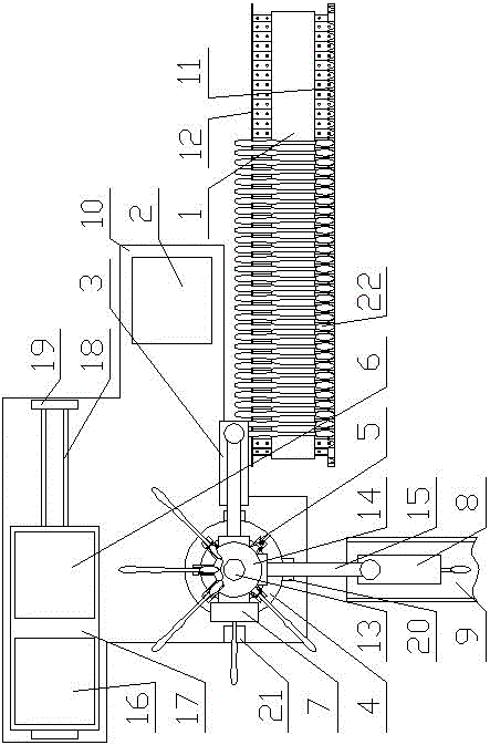
[0111] When the present invention is in use, when one end of the marking machine 16 of the slide plate 17 is attached to the limit block 19, that is, the inking device 6 corresponds to the marking station at this moment, and when it is close to the limit block 19 on the side of the marking machine 16 The signal sensor H of the signal sensor H does not get a signal, and the signal sensor G on the limit block 19 near the side of the inking device 6 gets a signal at the same time, then the inking device 6 and the gluing device 3 work, but the marking machine 16 does not work .

[0112]After the system is started, the motor C drives the conveyor belt 25 to move forward step by step. The operator places the toothbrush 22 on the conveyor belt 25 in sequence. The paint template 36 of the paint block 37 leaves the paint box 34, and then through the action of the piston B45, the paint block 37 is driven to stretch out to the top of the toothbrush handle of the toothbrush 22, and the pi...

Embodiment 2

[0120] When the present invention is in use, when one end of the inking device 6 of the slide plate 17 is attached to the limit block 19, that is, the marking machine 16 corresponds to the marking station at this time, when the limit block 19 on the side of the inking device 6 is close to The signal sensor G of the signal sensor G does not get a signal, and the signal sensor H on the limit block 19 near the side of the marking machine 16 gets a signal at the same time, then the inking device 6 and the gluing device 3 do not work, and the marking machine 16 works .

[0121] After the system is started, the motor C drives the conveyor belt 25 to move forward step by step, and the operator places the toothbrush 22 on the conveyor belt 25 in sequence. The motor A51 of the fetching device A3 drives the rotating base block 49 to rotate until the center line of the rotating base block 49 is in the same vertical plane as the toothbrush 22, and the piston rod D stretches out. The pisto...


PUM


Abstract

The invention discloses an automatic labeling machine for toothbrush handles. The automatic labeling machine comprises a conveying device, a station rotary disc and a discharging port sequentially, wherein a gluing device is arranged on one side of the conveying device; at least a feeding station, a labeling station, a code printing station and a discharging station are arranged on the periphery of the station rotary disc sequentially; toothbrushes on the conveying device are transferred to the feeding station through a gripping device A; toothbrushes on the discharging station are transferred to the discharging port through a gripping device B; a plurality of toothbrush head fixing devices are uniformly distributed on the station rotary disc which is rotationally connected onto a base; the gluing device, the feeding station, the labeling station, the code printing station and the discharging station are arranged on the base respectively; the discharging port is formed in one side of the base. With adoption of the structure, automatic production of the toothbrushes can be realized during labeling and code printing procedures, the labor intensity of an operator is reduced, and the production efficiency is increased.

Description

technical field [0001] The invention relates to the field of toothbrush production, in particular to an automatic marking machine for toothbrush handles. Background technique [0002] A toothbrush is a brush used to clean teeth. Generally all can add toothpaste to clean teeth on the toothbrush when brushing teeth, and toothbrush is the necessity article of people's daily life. And because the frequency of replacement of toothbrushes is relatively high in consideration of the hygienic condition and service life of toothbrushes, the market demand for toothbrushes is very large. [0003] In the process of toothbrush production, a label with certain information needs to be pasted on the handle of the toothbrush. In the current production enterprises, there is no special automatic label printing equipment, which needs to be done manually by the operator, or semi-automatically through the label printing machine. Production, resulting in low production efficiency, requires a larg...

Claims


Application Information

Patent Timeline
IPC IPC(8): A46D3/00B41F17/14A46B15/00
CPCA46B15/0085A46B2200/1066A46D3/00B41F17/14
Inventor 朱海英
Owner HUAIAN HUABANG PRECISION MACHINERY CO LTD
Why Eureka
Try Eureka