Eureka AIR delivers breakthrough ideas for toughest innovation challenges, trusted by R&D personnel around the world.

Temperature control system for reagent cabin of biochemical analyzer

A temperature control system, temperature control system technology, applied in the field of medical equipment, can solve the problems of long circulation pipeline, low refrigeration efficiency, low heat conduction efficiency of circulating water, etc., reduce equipment failure rate, suppress scale, etc., and facilitate The effect of troubleshooting

Active Publication Date: 2016-08-10
ZHONGSHENG SUZHOU MEDICAL INSTR
View PDF5 Cites 3 Cited by
  • Summary
  • Abstract
  • Description
  • Claims
  • Application Information

AI Technical Summary

Problems solved by technology

[0003] The existing refrigeration cycle method will produce several disadvantages: 1. The scale and bacteria generated on the circulation path will interfere with other flow paths and cause damage to the circulation pump, solenoid valve and other components (especially the finned water cooling head. The structure is easy to block and the circulation is not smooth); 2. The circulation pipeline is long, the cooling efficiency is not high, and the high temperature environment will exceed the working temperature of the reagent chamber (generally 5-8°C, and some large speed measuring equipment is at 4-12°C) ; 3. After the air bubbles are exhausted in the circulating water, it is difficult to judge the flow of the liquid, so it is difficult to check the normal working status of the circulating pump; 4. The heat conduction efficiency of the circulating water is low and volatilizes quickly, which will affect the copper and aluminum in the circulation pipeline. etc. are corrosive to a certain extent (copper rust, etc.)

Method used


Image

  • Temperature control system for reagent cabin of biochemical analyzer
  • Temperature control system for reagent cabin of biochemical analyzer
  • Temperature control system for reagent cabin of biochemical analyzer

Examples


Embodiment Construction

[0026] The preferred embodiments of the present invention will be described in detail below in conjunction with the accompanying drawings, so that the advantages and features of the present invention can be more easily understood by those skilled in the art, so as to define the protection scope of the present invention more clearly.

[0027] see Figure 1-Figure 5 , the embodiment of the present invention includes:

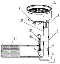
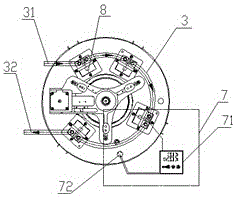
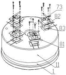
[0028] A temperature control system for a reagent chamber of a biochemical instrument, comprising: a refrigeration chamber 1, a refrigeration device 8, a circulation pipeline 3, a radiator 2 and a temperature control system 7, and the number of the refrigeration devices 8 is four groups and is evenly arranged in the refrigeration chamber 1, the refrigerating device 8 includes: a semiconductor cooling chip 83 in contact with the bottom of the cooling chamber 1, a water cooling head 82 arranged above the semiconductor cooling chip 83, and a pressure plate 81 arrange...


PUM


Abstract

The invention discloses a temperature control system for a reagent cabin of a biochemical analyzer. The temperature control system comprises a refrigeration cabin, refrigeration apparatuses, a circulation pipeline, a radiator and a temperature-control system, wherein the number of the refrigeration apparatus is three, and each refrigeration apparatus is arranged at the bottom of the refrigeration cabin and comprises a semiconductor refrigeration sheet contacting with the bottom of the refrigeration cabin, a water cooling head arranged above the semiconductor refrigeration sheet and a pressure plate arranged above the water cooling head; the circulation pipeline is used for connection among the refrigeration apparatuses and connection between the refrigeration apparatuses and the radiators; and the temperature-control system is used for monitoring the temperature of the refrigeration cabin and controlling the power of the semiconductor refrigeration sheet. Thus, the temperature control system for the reagent cabin of the biochemical analyzer can improve refrigeration efficiency, reduce intermediate water tanks and simplify a structure; the system is isolated from other flow paths, so mutual interference does not exist; and the pipeline is smooth and is convenient to maintain, so the failure rate of each execution element is reduced.

Description

technical field [0001] The invention relates to the field of medical equipment, in particular to a temperature control system for a reagent chamber of a biochemical instrument. Background technique [0002] At present, the temperature control of the reagent chamber of the biochemical analyzer mostly adopts two forms of air cooling and water cooling to ensure the conditions of reagent storage. The higher cooling efficiency is water cooling. The usual structure is to take away the heat generated by the semiconductor refrigerator through the circulation of the water tank, circulation pump and radiator to ensure the normal operation of the semiconductor refrigerator, and to achieve the low temperature control of the reagent chamber through the temperature controller. The water tank is generally shared with the water inlet tank of the equipment to simplify the structural layout. [0003] The existing refrigeration cycle method will produce several disadvantages: 1. The scale an...

Claims


Application Information

Patent Timeline
Patent Type & Authority Applications(China)
IPC IPC(8): B01L7/00
CPCB01L7/00B01L7/50B01L2300/185
Inventor 夏斌
Owner ZHONGSHENG SUZHOU MEDICAL INSTR
Why Eureka
Eureka Blog
Learn More