
High precision control system and method for forging oil press

A control system and high-precision technology, applied to the driving device of the forging press, etc., can solve the problems of slow system response, measurement of forging size deviation, and failure to consider frame deformation, etc., to achieve high control accuracy and fast system response. Effect

Active Publication Date: 2016-08-10
CHINA NAT HEAVY MACHINERY RES INSTCO
View PDF6 Cites 3 Cited by
  • Summary
  • Abstract
  • Description
  • Claims
  • Application Information

AI Technical Summary

Problems solved by technology

[0004] The purpose of the present invention is to solve the problem that the existing forging hydraulic press does not take into account the deformation of the frame when pressurizing, which leads to deviations in the actual measurement of the forging size and the slow response of the system

Method used


Image

  • High precision control system and method for forging oil press
  • High precision control system and method for forging oil press

Examples


Embodiment 1

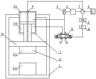
[0024] In order to solve the problem that the existing forging hydraulic press does not take into account the deformation of the frame when it is pressurized, which leads to deviations in the actual measurement of the forging size and the slow response of the system, such as figure 1 As shown, this embodiment provides a high-precision control system for forging hydraulic presses, including a press frame 1 and a movable beam 14 moving on the press frame 1. An anvil 2 is installed on the lower surface of the movable beam 14, and the upper surface passes through the plunger. Connected with a master cylinder 3, the master cylinder 3 is provided with a position sensor 4, the position sensor 4 is electrically connected to the adder-subtractor 7, and the adder-subtractor 7 is electrically connected to the input device 8, and the master cylinder 3 is connected to the proportional directional valve through a pipeline 11. The proportional directional valve 11 is electrically connected to...

Embodiment 2

[0028] On the basis of Embodiment 1, the inner chamber of the master cylinder 3 is divided into a master cylinder large chamber 3-1 and a master cylinder small chamber 3-2, and the master cylinder large chamber 3-1 is connected to the B port of the proportional directional valve 11, The small cavity 3-2 of the master cylinder is connected with the A port of the proportional directional valve 11, the P port of the proportional directional valve 11 is connected with the oil supply pipe 12, and the T port of the proportional directional valve 11 is connected with the oil return pipe 13.

[0029] Described type anvil 2 is made up of upper anvil 2-1 and lower anvil 2-2, and upper anvil 2-1 is fixed on the lower surface of movable beam 14, and lower anvil 2-2 is fixed on the lower beam of press frame 1.

[0030] It should be noted that, if figure 1 As shown, the lower anvil 2-2 is fixed on the press frame 1, the main cylinder 3 is fixed on the press frame 1, and when the main cylind...

Embodiment 3

[0032] On the basis of Embodiment 1, preferably, the input device 8 is a touch screen.


PUM


Abstract

The invention provides a high precision control system and method for a forging oil press. The high precision control system comprises a press frame and a movable transverse beam moving on the press frame, a mold anvil is installed on the lower surface of the movable transverse beam, a main cylinder is connected to the upper surface of the movable transverse beam through a plunger piston, and a position sensor is arranged on the main cylinder and electrically connected with an adder-subtractor; the adder-subtractor is electrically connected with an input device, the main cylinder is connected with a proportional direction valve through a pipe, and the proportional direction valve, an amplifier, a PID controller and the adder-subtractor are sequentially and electrically connected; and the pipe for connecting the main cylinder with the proportional direction valve is provided with a pressure sensor, and the pressure sensor, a frame deformation convertor and the adder-subtractor are sequentially and electrically connected. By means of the high precision control system and method for the forging oil press, the pressure of the main cylinder is monitored through the pressure sensor, the pressure of the main cylinder is converted into frame deformation Uk, the influences of the frame deformation Uk of the press on Ue are singly considered in the control process, and the control accuracy is higher; and when the pressure changes are larger, the system response speed is higher than that in the prior art.

Description

technical field [0001] The invention belongs to the technical field of free forging equipment, and in particular relates to a high-precision control system and method for a hydraulic forging machine. Background technique [0002] The forging manufacturing industry is the foundation of the national equipment manufacturing industry, and forging equipment technology is a necessary condition for improving the quality and production efficiency of forgings and reducing manufacturing costs. [0003] In the prior art, the position sensor installed in the main working cylinder is used to detect the position Uc of the upper anvil, and Uc is compared with the set value to obtain the difference Ue. In the prior art, all deviations Ue during pressurization are subjected to PID processing, The deformation Uk of the frame during pressurization is not considered separately. When the pressure is high, Uk is large, and the actual measurement of the forging size will find a large margin; when ...

Claims


Application Information

Patent Timeline
Patent Type & Authority Applications(China)
IPC IPC(8): B21J9/20B21J9/12
CPCB21J9/12B21J9/20
Inventor 牛勇张营杰范玉林冯东晓
Owner CHINA NAT HEAVY MACHINERY RES INSTCO
Learn More