Roof rainwater collecting system

A rainwater collection and water outlet technology, applied in waterway system, roof, roof drainage, etc., can solve the problems of no filter device, high system cost, lack of filter device in the system, etc.

Active Publication Date: 2016-08-10
JIANGSU UNIV
View PDF9 Cites 13 Cited by
  • Summary
  • Abstract
  • Description
  • Claims
  • Application Information

AI Technical Summary

Problems solved by technology

Chinese Patent No. CN103306333B discloses "a rainwater collection system and a building equipped with the rainwater collection system". Rainwater quality, the system only has a waste flow device, no filter device
Chinese Patent No. CN103397680B discloses "a fully automatic roof rainwater collection and purification device and method". Purification, the system uses a pulley block as the flow-abandoning part of the flow-abandoning device, and the stability is poor in actual use
[0004] Although the above-mentioned patents can realize roof rainwater collection, some systems lack filtering devices, some systems are complex, poor stability, or the system cost is too high, which has a certain impact on the popularization and application of rainwater collection devices

Method used


Image

  • Roof rainwater collecting system
  • Roof rainwater collecting system
  • Roof rainwater collecting system

Examples


Embodiment Construction

[0025] The present invention will be further described below in conjunction with accompanying drawing and specific embodiment:

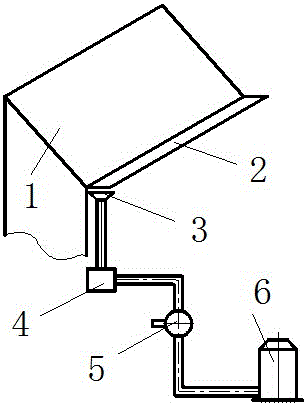
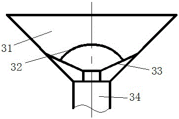
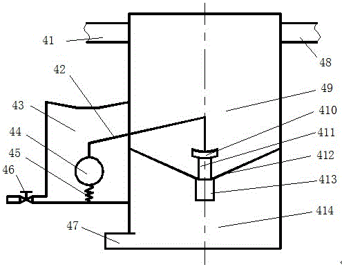
[0026] see figure 1 , a roof rainwater collection system, including a roof 1, a rain tank 2, a primary filter device 3, a waste flow device 4, a backwash filter device 5 and a rain barrel 6. The rain collecting tank 2 is installed on the lower edge of the roof 1 to collect the rainfall on the roof and guide the rain into the rainwater collection pipeline. The primary filter device 3 is non-contact installed at the lower part of the outlet of the rain collecting tank 2. The primary filter device 3 is the entrance of the rainwater collection pipeline, which can also filter large debris such as leaves to prevent debris from entering the water passage and causing pipeline blockage. The primary filter device 3, the discarding device 4, and the backwashing filter device 5 are installed in series through the water pipeline. To meet the needs of life or p...


PUM


Abstract

The invention discloses a roof rainwater collecting system, which comprises a roof, a rainwater collecting groove, a primary filtering device, a split-flow device, a reverse flushing filtering device and a rainwater collecting barrel, wherein the rainwater collecting groove is formed at the lower edge of the roof; the primary filtering device is arranged at the lower part of a water outlet opening of the rainwater collecting groove in a non-contact way, and can be used for intercepting sundries with large sizes to prevent a water passing pipeline from being blocked; an intercepting regulating rod of the split-flow device can intercept the rainwater from entering a regulating cavity so as to raise a floating ball valve; the early stage rainwater split-flow and the later stage pure water collection can be realized; the reverse flushing device is provided with a first filtering screen, a second filtering screen and a flushing device; the filtration on the collected rainwater can be realized; when pipeline accumulated water increase is caused by the blockage of the first filtering screen and the second filtering screen by filtering sundries, under the rainwater static pressure effect in the water passing pipeline, a piston is driven to move, a flushing outlet is opened; and the automatic flushing on the reverse flushing device can be realized. The roof rainwater collecting system has the dual filtering and early stage rainwater split-flow function; and the rainwater collection and utilization efficiency can be improved.

Description

technical field [0001] The invention relates to a water-saving and environment-friendly system, in particular to a roof rainwater collection system. Background technique [0002] With the continuous economic development and rapid population growth, the demand for industrial, agricultural and domestic water supply is constantly escalating, and the water crisis has become one of the hot issues of globalization. Many cities in our country are in a state of water shortage, and rainwater, as a long-term and stable non-traditional water source, is easy to obtain, easy to handle, and has a huge amount. The use of rainwater can not only alleviate the shortage of water resources in cities, but also prevent urban flood disasters, and play an important role in the virtuous cycle and sustainable development of urban water environment complex ecosystems. Rainwater can not only be used for domestic and industrial production, but also can be used as community greening, irrigation, cleanin...

Claims


Application Information

Patent Timeline
Patent Type & Authority Applications(China)
IPC IPC(8): E03F1/00E04D13/04
CPCE03F1/00E03F2201/10E04D13/0404
Inventor 陈超李红
Owner JIANGSU UNIV
Why Eureka
Try Eureka