Novel steel pipe column and shaped steel beam assembling method

An assembly method and a technology of steel pipe columns, which are applied in the direction of construction and building construction, can solve the problems of inconvenient assembly, low load action, and high cost, and achieve the effects of increasing bearing capacity, good seismic ductility, and improving seismic performance and ductility

Inactive Publication Date: 2016-08-10
CHINA UNIV OF MINING & TECH
View PDF5 Cites 6 Cited by
  • Summary
  • Abstract
  • Description
  • Claims
  • Application Information

AI Technical Summary

Problems solved by technology

[0003] In order to solve the problems of complex assembly of steel pipe columns and shaped steel pipes, low load action, and relatively high cost in current construction projects; this invention provides a new assembly method for steel pipe columns and shaped steel beams
This method is suitable for the assembly connection between steel pipe columns with closed sections and steel beams with open sections. It can solve the problem that closed sections are not easy to assemble, effectively improve the seismic performance and ductility of joints, increase the bearing capacity of joints, and protect steel pipe columns in static conditions. There will be no brittle failure under force or earthquake, thereby ensuring that the steel frame structure has good seismic ductility

Method used


Image

  • Novel steel pipe column and shaped steel beam assembling method
  • Novel steel pipe column and shaped steel beam assembling method
  • Novel steel pipe column and shaped steel beam assembling method

Examples


Embodiment Construction

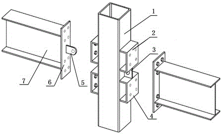
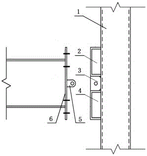
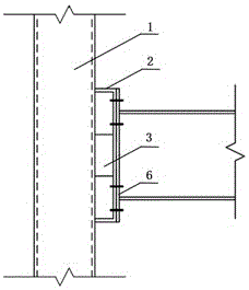
[0014] A new assembly method of a steel pipe column and a shaped steel beam, comprising: a steel pipe column 1, an upper flange U-shaped steel or channel steel 2, a shear web 3, a lower flange U-shaped steel or a channel steel 4, and beam end lugs 5 , beam end plate 6, open-shaped steel beam 7; a new assembly method of a steel pipe column and a steel beam, on both sides of a steel pipe column 1 with a closed section, a plurality of bolts are welded vertically to the symmetrical axis respectively The U-shaped steel or channel steel 2 of the upper flange of the hole is welded with the U-shaped steel or channel steel 4 of the lower flange with multiple bolt holes at its lower part, and the U-shaped steel or channel steel 2 of the upper flange and the lower flange The shear web 3 with bolt holes is welded in the gap between the U-shaped steel or the channel-shaped steel 4; the open-shaped steel beam 7 is I-shaped, H-shaped, and groove-shaped, and a beam end plate 6 is welded at the...


PUM


Abstract

The invention discloses a novel steel pipe column and shaped steel beam assembling method. Top flange U-shaped steel or channel steel provided with multiple bolt holes is vertically welded to the two sides faces of a steel pipe column with the section closed and is symmetrical about the axis, lower flange U-shaped steel or channel steel provided with multiple bolt holes is correspondingly welded to the lower portion of the steel pipe column, and a shear web provided with bolt holes is welded to the gap between the top flange U-shaped steel or channel steel and the lower flange U-shaped steel or channel steel; an open type steel beam has an open section, a beam end plate is welded to the end of one side of the open type steel beam, a beam end lug plate is welded to the middle of the beam end plate, bolt holes in the beam end plate correspond to those in the top flange U-shaped steel or channel steel and the lower flange channel steel, and the beam end lug plate corresponds to the bolt holes in the shear web. The method is suitable for assembly and connection between the steel pipe column with the closed section and the steel beam with the open section, the anti-seismic property and ductility of a joint can be improved, the bearing capacity of the joint can be improved, brittle failure of the steel pipe column under static force or earthquake action is avoided, and then high earthquake-resistant ductility of a steel frame structure is guaranteed.

Description

technical field [0001] The invention relates to a construction engineering technology, in particular to a novel assembly method of a steel pipe column and a shaped steel beam. Background technique [0002] Steel pipe columns have the advantages of reasonable stress, beautiful appearance, and convenient anti-corrosion and fire-resistant treatment. They are widely used in towers, bridges, public buildings, medium and high-rise buildings and high-rise structures. However, due to the closed section of the steel pipe column, it is difficult to achieve direct assembly connection with the H-shaped steel beam. At present, the commonly used joint connection methods of steel pipe columns and H-shaped steel beams are: diaphragm type, rib plate type, sleeve type, through-bolt type, single-sided bolt type, etc. Among the above methods, the diaphragm type and the rib plate type connection have higher rigidity and bearing capacity, but the construction is more complicated, and there is a ...

Claims


Application Information

Patent Timeline
Patent Type & Authority Applications(China)
IPC IPC(8): E04B1/58
CPCE04B1/2403E04B2001/2415E04B2001/2418E04B2001/2454
Inventor 常鸿飞夏军武祝华权徐博陈晓淼路振花彭康佑
Owner CHINA UNIV OF MINING & TECH
Why Eureka
Try Eureka