A tidal level adaptive floating pendulum wave power generation system

A power generation system, self-adaptive technology, applied in the direction of ocean energy power generation, engine function, engine components, etc., can solve the problems of not considering the influence of the wave absorption efficiency of the floating body, changing the attitude, and not having it, so as to reduce the probability of being damaged, Optimize the appearance design and avoid the effect of pollution

Inactive Publication Date: 2018-02-06
ZHEJIANG UNIV
View PDF6 Cites 0 Cited by
  • Summary
  • Abstract
  • Description
  • Claims
  • Application Information

AI Technical Summary

Problems solved by technology

However, the working condition of the wave energy generation device on the shore is easily affected by the sea tide level
Existing shore wave power generation devices cannot achieve optimal working conditions when the tide level is higher or lower than the design water level
[0003] On the other hand, many of the existing shore wave power generation devices do not consider the influence of the shape of the floating body on the wave absorption efficiency, and often use the simplest shapes such as cylinders and cubes.
Even if the shore wave energy generation device with the shape of the wave-absorbing floating body is optimally designed, it does not have the function of changing the posture with the change of the tide level, and the advantages of the optimized wave-absorbing shape cannot be maximized

Method used


Image

  • A tidal level adaptive floating pendulum wave power generation system
  • A tidal level adaptive floating pendulum wave power generation system
  • A tidal level adaptive floating pendulum wave power generation system

Examples


Embodiment Construction

[0026] Below in conjunction with accompanying drawing and specific embodiment the present invention is described in further detail:

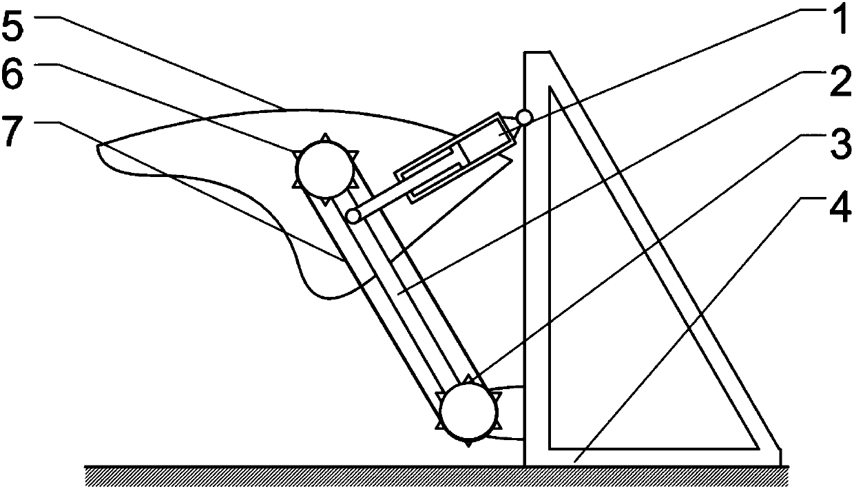
[0027] Such as figure 1 As shown, the present invention includes a floating body structure floating on the sea surface and a hydraulic system connected to the floating body structure for energy conversion. The connecting rod 2 between the two synchronous pulleys; the floating body 5 is a sealed structure welded by internal hollow steel, the floating body 5 is hinged with the bracket 4, and the bracket 4 is a frame fixed on the shore or the seabed or one side of a large floating body The structure plays a supporting role for the whole system, so that the floating body 5 swings around the fulcrum on the support with the ups and downs of the waves; the connecting rod 2 is connected with the hydraulic system, and converts the mechanical energy of the floating body 5 into hydraulic energy and transmits it to the hydraulic system for power generation....


PUM


Abstract

The invention discloses a floating swing type wave power generation system self-adaptive to the tide level. The floating swing type wave power generation system comprises a floating body structure floating on the sea surface and a hydraulic system connected with the floating body structure and used for energy conversion. The floating body structure comprises a floating body, a support, a pair of synchronous belt wheels synchronously connected through a synchronous belt, and a connection rod connected between the two synchronous belt wheels. The floating body is of a sealed structure formed by welding hollow steel. The floating body is hinged to the support fixed to the coast or a large floating body so that the floating body can swing around a fulcrum along with fluctuation of waves. The connection rod is connected with the hydraulic system, converts the mechanical energy of swinging of the floating body into hydraulic energy, and transmits the hydraulic energy to the hydraulic system for power generation. By means of the floating swing type wave power generation system, the high wave energy absorption efficiency can be achieved, the adaptive capacity for the tide level changes within a certain range is high, pollution to the environment is reduced, and the probability that the floating swing type wave power generation system itself is damaged is lowered.

Description

technical field [0001] The invention designs a wave energy generating device, and more specifically relates to a floating pendulum type wave energy generating system with self-adaptive tide level. Background technique [0002] The wave energy generation devices used for wave energy development can be divided into shore wave energy generation devices, nearshore wave energy generation devices and offshore wave energy generation devices according to their deployment locations. In comparison, shore wave energy generation devices can be more easily connected to the grid and easier to maintain. However, the working condition of the wave energy generating device on the shore is easily affected by the tide level of seawater. Existing shore wave power generation devices cannot achieve optimal working conditions when the tide level is higher or lower than the design water level. [0003] On the other hand, many of the existing shore wave power generation devices do not consider the ...

Claims


Application Information

Patent Timeline
Patent Type & Authority Patents(China)
IPC IPC(8): F03B13/18
CPCF03B13/187F05B2260/406Y02E10/30
Inventor 张大海杨景陈鹰李伟谭铭梁辉
Owner ZHEJIANG UNIV
Why Eureka
Try Eureka