Improved optical fiber turbine flowmeter

An improved technology of a turbine flowmeter, which is applied in the direction of measuring flow/mass flow, liquid/fluid solid measurement, volume/mass flow generated by mechanical effects, etc. It can solve the problems of anti-pollution on the end face of the fiber optic probe, and improve the range ratio and measurement sensitivity, solving pollution prevention problems, and improving the effect of driving torque

Active Publication Date: 2016-08-10
NORTHEASTERN UNIV +2
View PDF8 Cites 3 Cited by
  • Summary
  • Abstract
  • Description
  • Claims
  • Application Information

AI Technical Summary

Problems solved by technology

[0006] The purpose of the present invention is to meet the needs of medium and small flow measurement occasions in actual industrial production, reduce the initial flow rate of traditional turbine flowmeters, widen its range ratio and improve its sensitivity, and solve the problem of anti-pollution on the end face of the optical fiber probe of traditional optical fiber turbine flowmeters. An improved turbine flowmeter structure is proposed

Method used


Image

  • Improved optical fiber turbine flowmeter
  • Improved optical fiber turbine flowmeter
  • Improved optical fiber turbine flowmeter

Examples


Embodiment Construction

[0022] specific implementation plan

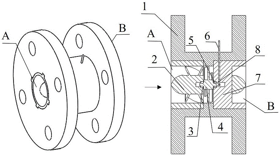
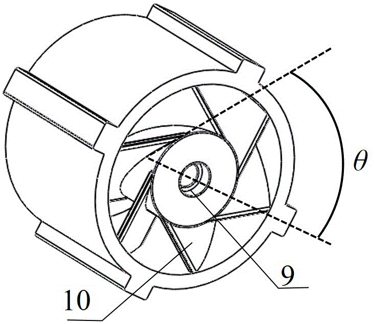
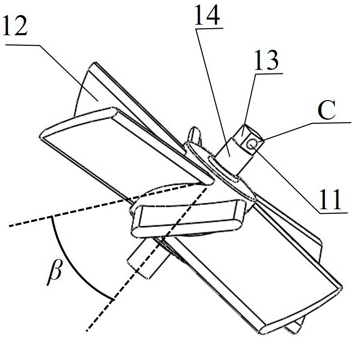
[0023] In order to make the purpose, technical solution and advantages of the present invention clearer, the specific structure, principle and optimization process of the present invention will be further described in detail below in conjunction with specific embodiments and with reference to the accompanying drawings. Such as figure 1 , figure 2 , image 3 , Figure 4 As shown, an improved fiber optic turbine flowmeter includes a casing 1, a front guide element 2 placed in the casing 1, a front bearing 3, a rotating turbine 4, a rear bearing 5, an optical fiber 6, and a rear flow guide element 7. The front guide element 2 guides the fluid so that the fluid can act vertically on the rotating turbine blades 12 so that the rotating turbine 4 can obtain the maximum driving torque. The rear guide element 7 acts as a rectifier, reducing the impact of the rotating fluid passing through the rotating turbine 4 on the devices installed in the ...


PUM


Abstract

The invention provides an improved optical fiber turbine flowmeter. The improved optical fiber turbine flowmeter is composed of a shell (1), a front flow guide element (2), a fore bearing (3), a rotating turbine (4), a rear bearing (5), optical fiber (6) and a rear flow guide element (7). The helix angle beta of rotating turbine blades (12) of the turbine flowmeter is designed to be 45 degrees, and the helix angle beta of front flow guide element blades (10) is designed to be 45 degrees, so that driving moment of the rotating turbine (4) is effectively increased, the starting flow rate is reduced, the range ratio is increased, and sensitivity is improved. In addition, the optical fiber (6) is sealed in rear flow guide element blades (16), an optical fiber probe end face (8) is effectively prevented from being polluted by fluid, and therefore the flowmeter can operate reliably for a long time. Flattening, silver film plating and trepanning are conducted in a 2mm region at the tail end a rotating shaft (14) to obtain a through hole (11) and a silver film plated surface (13) of the rotating shaft, different reflection rates are provided, rotating speed signals are converted into optical signals of pulse changes, and the rotating speed of the turbine is measured by measuring the reflected light impulse frequency.

Description

technical field [0001] The invention relates to an improved fiber optic turbine flowmeter based on a traditional turbine flowmeter, and belongs to the technical field of flow measurement. Background technique [0002] Due to its small size, simple structure and low price, turbine flowmeters are widely used in petroleum, pharmaceutical, chemical and other fields, and can realize the flow measurement of water, oil, wine and other pipelines. At the same time, it has the advantages of high precision and reliable performance, and can be used as a calibration component in high-tech fields such as aerospace. However, the turbine flowmeter is limited by the turndown ratio and has a large dead zone, which limits its application range. Therefore, reducing the initial flow rate and expanding the linear working area will be an important measure to improve the performance of the turbine flowmeter and expand the application range. (Document 1: Xie Shengqiu, Zhang Shirong, Huang Shuwang,...

Claims


Application Information

Patent Timeline
Patent Type & Authority Applications(China)
IPC IPC(8): G01F1/10
CPCG01F1/103
Inventor 吕日清顾亚飞赵勇王孟军杨华丽杨洋
Owner NORTHEASTERN UNIV
Why Eureka
Try Eureka