
Eureka
For R&D, Eureka makes reading and utilizing patents & technical documents easy.
Eureka AIR
Designed for self-driven R&D workflows. Generate viable solutions, solve complex R&D challenges, empower your innovation with AI.

Eureka Materials
Designed for material experts only. Revolutionize your material R&D, from search, analyze, to developing new materials.

TechResearch
Generate reliable direction feasibility study reports for your R&D in just a few steps.

TechSeek
Discover and master advanced knowledge NOW. Basics, ideas, possibilities, all at once.

TechMind
As an expert in R&D Theories, TechMind can generates customized viable solutions instantly.

TechRisk
Analyze your overall solution with one click, know your potential R&D risks in advance.

TechMonitor
Get weekly tech updates, stay abreast of the latest tech innovations and key insights.
Device for measuring temperature in molten metal
A technology of molten metal and metal, which is applied in the field of long-term thermocouple equipment, can solve the problems of expensive and other problems, and achieve the effect of accurate temperature measurement, increased life expectancy, and precise control
- Summary
- Abstract
- Description
- Claims
- Application Information
AI Technical Summary
Problems solved by technology
Method used
Image

Examples
Embodiment Construction
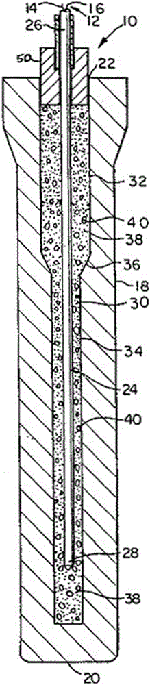
[0008] Referring to the drawings, wherein like reference numerals refer to like elements throughout, in figure 1 Among them, 10 represents the molten metal temperature measuring device according to the present invention.
[0009] Such as figure 1 Best shown, molten metal temperature measuring device 10 includes a thermocouple element, a portion of which is indicated generally at 12 . Typically, thermocouple element 12 consists of a positive element and a negative element (not shown). For the sake of discussion, in figure 1 In , the positive component is shown as positive lead 14 and the negative component is shown as negative lead 16 .
[0010] Positive lead wire 14 and negative lead wire 16 are generally composed of two different metal materials, such as platinum, platinum-rhodium alloy, nickel-chromium alloy, copper-nickel alloy, iron, nickel-aluminum alloy, and copper. Thermocouple element 12 is enclosed in a doublet (not shown) to isolate positive lead 14 from negative...
PUM
 Abstract
Description
Claims
Application Information
 - R&D Engineer
- R&D Manager
- IP Professional
- Industry Leading Data Capabilities
- Powerful AI technology
- Patent DNA Extraction
Browse by: Latest US Patents, China's latest patents, Technical Efficacy Thesaurus, Application Domain, Technology Topic, Popular Technical Reports.
© 2024 PatSnap. All rights reserved.Legal|Privacy policy|Modern Slavery Act Transparency Statement|Sitemap|About US| Contact US: help@patsnap.com