
Clamping device for clamping test piece and use method of clamping device

A technology of clamping device and clamping sheet, which is applied in the direction of measuring devices, instruments, scientific instruments, etc., can solve the problems of difficulty in controlling the dimensional accuracy of parts, reduced fatigue life, and large size of fatigue test pieces, so as to improve clamping stability The effect of high quality and accuracy, easy disassembly and compact structure

Active Publication Date: 2016-08-10
COMAC +1
View PDF4 Cites 5 Cited by
  • Summary
  • Abstract
  • Description
  • Claims
  • Application Information

AI Technical Summary

Problems solved by technology

[0003] The multi-step thin-walled structure is a typical lightweight structure of aircraft skin panels. In the past, the skin panels were chemically milled to corrode part of the metal sheet to obtain the multi-step thin-walled parts required for the design. However, the chemical milling process The release of the anti-fatigue residual stress on the surface of the plate reduces the fatigue life, the dimensional accuracy of the parts is difficult to control, and the process pollution is serious, which does not meet the green and environmental protection manufacturing requirements. Multi-step structure, research on the fatigue performance and reliability of thin-walled flat parts after mechanical milling, and provide basic data for the design, forming and manufacturing process specifications of high-performance, long-life aluminum-lithium alloy skin panels and technical support
[0004] Due to the existence of milling slots, the size of the fatigue specimen designed in the fatigue test is relatively large, and the clamps of the general fatigue testing machine cannot meet the width requirements of the specimen; Sliding, so an effective and stable clamping method is the primary problem to be solved

Method used


Image

  • Clamping device for clamping test piece and use method of clamping device
  • Clamping device for clamping test piece and use method of clamping device
  • Clamping device for clamping test piece and use method of clamping device

Examples


Embodiment Construction

[0031] The present invention will be further described in detail below with reference to the drawings and specific examples. For the convenience of discussion, "up", "down", "left", and "right" are used to indicate the position in each schematic diagram, which is conducive to the development of the discussion.

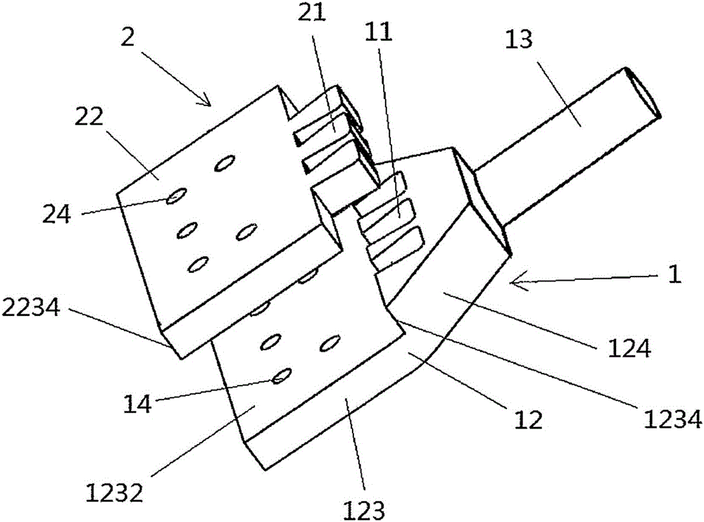
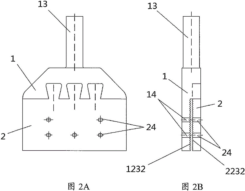
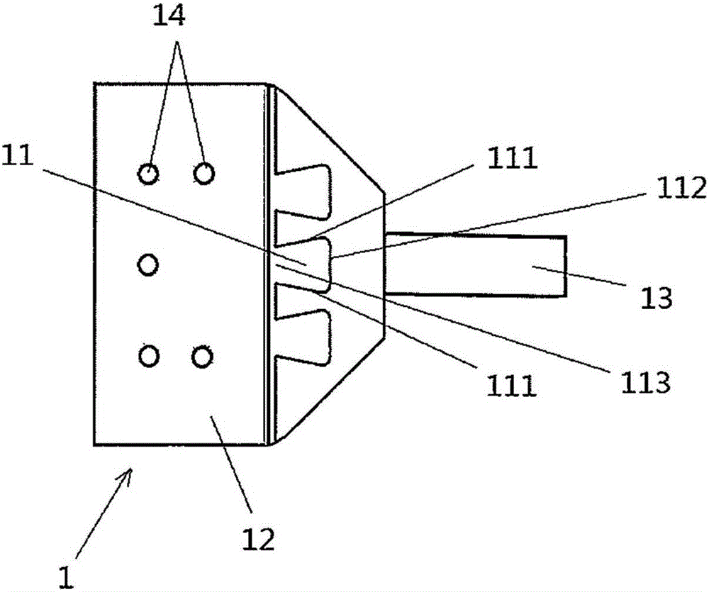
[0032] Such as figure 1 What is shown is the situation when the upper clamping piece 2 and the lower clamping piece 1 of the clamping device of the present invention are separated. Correspondingly, Figure 2A with Figure 2B This book is a front view and a side view when the upper clamping piece 2 and the lower clamping piece 1 of the clamping device of the present invention are combined. At the same time, you can refer to Figure 3A with Figure 3B , Respectively show the lower clamping piece 1 and the upper clamping piece 2 of the clamping device of the present invention.

[0033] in figure 1 Among them, the preferred clamping device of the present invention includes: an...


PUM


Abstract

The invention provides a clamping device which comprises an upper clamping piece and a lower clamping piece .The upper clamping piece comprises an upper clamping piece body, upper clamping piece through holes are formed in the upper clamping piece body in the thickness direction, and one side face of the upper clamping piece body is provided with dovetail tenons; the lower clamping piece comprises a lower clamping piece body and a testing machine clamping part which is used for being clamped in an external testing machine, the lower clamping piece body further comprises a lower clamping piece body base part and a lower clamping piece body protruding part, lower clamping piece through holes are formed in the lower clamping piece body base part in the thickness direction, the lower clamping piece body protruding part is provided with dovetail mortises, and the depth of each dovetail mortise is equal to the height difference; the dovetail tenons can be aligned with the dovetail mortises, at the moment, the upper clamping piece through holes can be aligned with the lower clamping piece through holes .The clamping device has the advantages of being compact in structure and accurate in positioning .The invention further provides a corresponding clamping method, and the clamping stability and accuracy of a test piece to be tested are greatly improved.

Description

Technical field [0001] The invention relates to a clamping device for clamping a test piece and a use method thereof, in particular to a clamping device for clamping a thin-walled fatigue test piece and a use method thereof. Background technique [0002] In order to meet the comprehensive requirements of safety, economy, comfort, and environmental protection, in the selection of airframe materials and structures for new commercial aircraft, on the one hand, lightweight materials with low density and high specific strength such as aluminum alloy and aluminum-lithium alloy are selected, and a large number of Using multi-step thin-walled structures, such as the nose, middle and rear fuselage skins, etc., by partially thinning the skin panels to form a multi-step thin-walled structure, the weight of the skin panels can be reduced by more than 40%. [0003] Multi-step thin-walled structure is a typical lightweight structure of aircraft skin siding. In the past, the skin siding was chemi...

Claims


Application Information

Patent Timeline
Patent Type & Authority Applications(China)
IPC IPC(8): G01N3/04
CPCG01N3/04G01N2203/0405G01N2203/0423
Inventor 陈洁孙中刚马超吴鹏程李小强宋楠李东升
Owner COMAC
Learn More