
Fall impact mitigating device for chip components, and wire jigs

A wire and relaxation technology, applied in the field of drop impact mitigation devices, can solve the problems of time-consuming movement, large-scale and complicated devices, etc.

Active Publication Date: 2016-08-10
MURATA MFG CO LTD
View PDF2 Cites 0 Cited by
  • Summary
  • Abstract
  • Description
  • Claims
  • Application Information

AI Technical Summary

Problems solved by technology

[0007] However, in the case of the chute device described in Patent Document 1, there are the following technical problems: (1) In order to sufficiently alleviate the impact of falling, it is necessary to provide a very long conveyance path; Therefore, it takes a lot of time to move. (3) It is necessary to connect a plurality of conveyance paths with hinge shafts so that they can be rotated. Therefore, the device becomes larger and more complicated.

Method used


Image

  • Fall impact mitigating device for chip components, and wire jigs
  • Fall impact mitigating device for chip components, and wire jigs
  • Fall impact mitigating device for chip components, and wire jigs

Examples


no. 1 example -

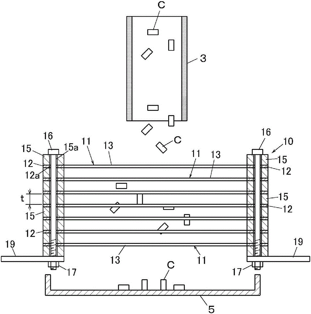
[0041] figure 1 , figure 2 The first embodiment of the drop impact mitigation device of the present invention is shown. This device is used to alleviate the drop impact of a chip component C such as a multilayer ceramic capacitor having a size of 0.5×0.5×1.0 mm. in addition, figure 1 It is illustrated for easy understanding, and the dimensional relationship between the chip component C and each member is different from the actual one.

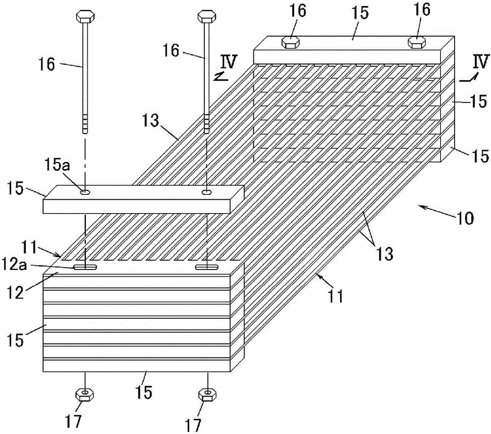
[0042] The impact mitigation device 1 includes: a dropping cylinder 3 for dropping the chip parts C to a predetermined position; a wire assembly 10 for receiving the chip parts C dropped in the dropping cylinder 3 and The chip component C is decelerated and passed through the above-mentioned wire assembly 10 ; and the recovery unit 5 recovers the chip component C passing through the wire assembly 10 . A plurality of chip components C are continuously dropped onto the wire assembly 10 through the drop cylinder 3 . The wire assembly 10 is...

no. 2 example -

[0053] Figure 8 A second embodiment of a wire assembly is shown. exist figure 2 In the present invention, the wire assembly 10 is constituted by stacking a plurality of wire jigs 11 with the separator 15 interposed therebetween, but the present invention is not limited thereto. In the wire assembly 20 of this embodiment, as Figure 8As shown, supports 21 for individually supporting the frame portion 12 of the wire clamp 11 are provided, and both end portions 21 a of the plurality of supports 21 are fixed to standing side plates 24 . Specifically, the contact plate 22 is arranged on the frame portion 12 of the wire rod clamp 11 , and the frame portion 12 is fixed to the support 21 with screws 23 . Preferably, screw holes 21c to be screwed with the screws 23 are formed in the support member 21 in advance. When fixing the wire clamp 11 to the support 21 , the position of the wire clamp 11 can be adjusted in a direction perpendicular to the wire longitudinal direction by usi...


PUM


Abstract

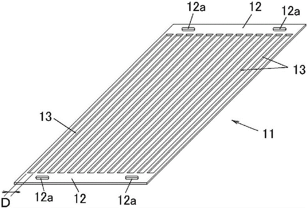
In the present invention, a fall impact mitigating device that mitigates the impact of falling chip components (C) is provided with a wire aggregate (10) formed by the accumulation of a plurality of wire jigs (11). The wire jigs (11) have a plurality of wires (13) that are disposed in parallel and set apart at intervals through which the chip components (C) can pass. The wire jigs (11) are obtained by processing a base material of a certain thickness to integrally form a pair of frames (12) and the plurality of wires (13) extending in parallel between the frames. When the chip components (C) are made to fall on top of the wire aggregate (10), the chip components (C) collide with the wires (13) of any of the wire jigs (11), and the collision with the wires causes the force of impact to be mitigated. The chip components easily pass through the spaces between wires, thereby reducing the frequency of collisions with subsequent chip components and preventing the chip components from cracking or chipping.

Description

technical field [0001] The present invention relates to a drop impact mitigating device capable of alleviating the drop impact of a dropped chip component and blocking it while suppressing damage or deformation of the chip component. The chip parts of the present invention are not limited to finished chip parts, but also include intermediate parts (for example, molded or fired chips, etc.). Background technique [0002] When conveying chip components such as multilayer ceramic capacitors in a manufacturing process, it may be necessary to transfer the chip components from a conveying line having a certain height to another conveying line having a lower height than the conveying line. Therefore, if Figure 10 As shown, there is a device: a plurality of conveyor belts 101, 102, 103 are arranged in multiple layers in the vertical direction, and the chip parts C carried on the conveyor belt 101 of the uppermost layer are dropped on the belt 102 of the next layer, The chip compon...

Claims


Application Information

Patent Timeline
IPC IPC(8): B65G11/20
CPCH01G13/00B65G69/16B65G2207/28H05K13/02B65G2207/42B65G2201/02B65G11/203B65G47/19B65G2814/0205H05K13/028B65G47/52
Inventor 秋本茂
Owner MURATA MFG CO LTD
Learn More