Supercharge Your Innovation With Domain-Expert AI Agents!

Coil

A coil and coil support technology, applied in the direction of coil, direct mass flow meter, liquid/fluid solid measurement, etc., can solve the problems of damaging the coil wire, increasing, destroying the coil, etc.

Active Publication Date: 2016-08-10
ENDRESS HAUSER FLOWTEC AG
View PDF75 Cites 1 Cited by
  • Summary
  • Abstract
  • Description
  • Claims
  • Application Information

AI Technical Summary

Problems solved by technology

Firstly, this is combined with a correspondingly increased risk of creating unrecognized, defective solder connections
Moreover, in the case of soldering, brazing of the connecting wires to the coils at the installation site, there is tearing of the most often very thin coil wires, corresponding damage to the likewise only very thin insulation of the coil wires and thus damage Increased risk of even breaking the coil

Method used


Image

  • Coil
  • Coil
  • Coil

Examples


Embodiment Construction

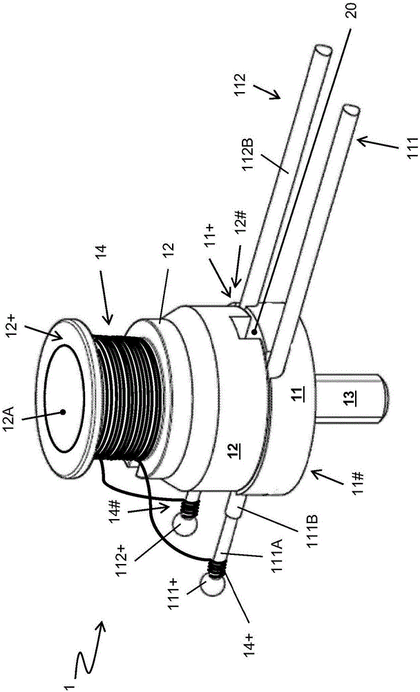
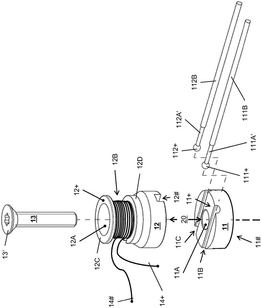
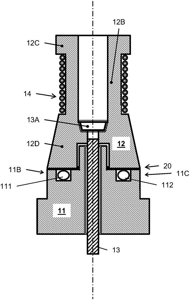
[0051] figure 1 , 2 Shown in and 3 are examples of embodiments of the coil 1 according to the invention, eg coils which can be used as part of vibratory measuring transducers, correspondingly electronic vibratory measuring devices formed from vibrating measuring transducers.

[0052] The coil 1 includes: a platform 11, the platform 11 has a first end 11+ formed by a first end face and a second end 11# away from the end 11+ and formed by a second end face, for example, a second end face parallel to the first end face; A coil support 12, the coil support 12 has a first end 12+ formed by a first end face and a second end 12# that is away from the end 12+ and is formed by a second end face, such as a second end face parallel to the first end face; and The coil supports a wound coil wire 14 of electrically conductive material, eg copper or a copper alloy or platinum or a platinum alloy. The platform 11 - here exemplified as a cylinder, respectively a disk - can be produced, for e...


PUM


Abstract

The coil (1) comprises a main body (11) with a passage opening (11A; 11A') which extends from one end (11+) of the main body, which end is formed by a first end face, to an end (11#) of the main body, which end is distal from said end (11+) and is formed by a second end face, comprises a coil former (12) with a passage opening (12A) which extends from one end (12+) of the coil former, which end is formed by a first end face, to an end (12#) of the coil former, which end is distal from said first end and is formed by a second end face. The coil former (12) is arranged relative to the main body (11) such that the second end face of the coil former faces the main body and an intermediate space (20) is formed between the second end face of the coil former and the first end face of the main body, and that the passage opening (12A) in the coil former is in alignment with the passage opening (11A) in the main body. The coil (1) additionally comprises a screw (13), which is received both by the passage opening in the coil former and also the passage opening in the main body, for mechanically connecting the coil former and the main body, comprises a coil of wire which is wound around the coil former and is composed of an electrically conductive material, and also comprises at least two connection lines (111, 112) which are each positioned in portions in the intermediate space which is formed between the coil former and the main body, and of which one connection line (111) has at least one core (111A) which is electrically conductively connected to one end (14+) of the coil of wire and is composed of electrically conductive material, and of which one connection line (112) has at least one core (112A) which is electrically conductively connected to one end (14#) of the coil of wire and is composed of electrically conductive material. The coil is also intended, in particular, for use in a vibration-type measurement transducer.

Description

technical field [0001] The invention relates to a coil, in particular a coil for use in a measuring transducer of the vibration type, in particular also a coil suitable for forming an oscillation exciter and / or an oscillation sensor. Furthermore, the invention relates to a vibrating measuring transducer having such a coil. Background technique [0002] Electronic vibratory measuring devices are used in industrial measurement technology, especially also in connection with the control and monitoring of automated manufacturing processes, for the highly precise determination of one or more of the measured variables, especially those flowing in process lines such as pipes Mass flow, density and / or viscosity of a medium such as a liquid or gas. Electronic vibratory measuring devices are usually formed by means of measuring device electronics, which are most often formed by means of at least one microprocessor, and a measuring transducer of the vibration type, which is electricall...

Claims


Application Information

Patent Timeline
IPC IPC(8): G01F1/84G01N9/00G01N11/16H01F5/04
CPCG01F1/8409G01N9/002H01F5/04H01F5/02H01F27/06G01F1/8422G01N11/16
Inventor 恩尼奥·比托格哈德·埃克特
Owner ENDRESS HAUSER FLOWTEC AG
Features
  • R&D
  • Intellectual Property
  • Life Sciences
  • Materials
  • Tech Scout
  • Unparalleled Data Quality
  • Higher Quality Content
  • 60% Fewer Hallucinations
Learn More