Driven electrochemical cell for electrolyte state of charge balance in energy storage devices
An electrochemical and electrolyte technology, applied in electrolyte flow processing, electrochemical generators, fuel cells, etc., can solve problems such as loss, imbalance between positive and negative electrolytes, and unbalanced performance
- Summary
- Abstract
- Description
- Claims
- Application Information
AI Technical Summary
Problems solved by technology
Method used
Image

Examples
example 12
[0083] Example 1.2 - Preparation of an effective area of 25cm 2 Experimental procedure of the flow battery pack
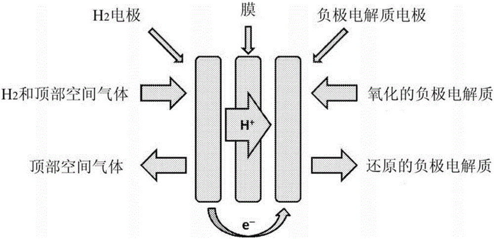
[0084] The present invention involves the use of two electrochemical cells, a primary electrochemical cell that performs the charge / discharge function of an energy storage device and a secondary cell that maintains the SOC balance of the electrolyte in the primary cell. The secondary battery in the present invention takes the form of a powered, hydrogen scavenging battery that can be coupled to the battery system to avoid electrolyte imbalances that would occur during operation of the primary battery.
[0085] Non-limiting examples of the primary battery of the present invention are described herein. Designed for 25cm 2 The active area and battery hardware for acid flow improvement was purchased from Fuel Cell Technologies (Albuquerque, NM). MGL 370 carbon paper was purchased from Fuel Cell Earth (Stoneham, MA) and spray coated with Mogul-L High Surface Area C...
example 13
[0087] Example 1.3 Prepare an effective area of 25cm 2 Experimental procedure for additional batteries
[0088] Non-limiting examples of second or additional batteries for use in the present invention are described herein. Designed for 25cm 2 The active area and acid flow modified battery hardware was purchased from Fuel Cell Technologies (Albuquerque, NM). Use a Pt loading of 0.3mg / cm by coating on one side 2 Membrane electrode assemblies (Ion-Power, Newcastle, DE) were composed of NR-212 cation exchange membranes with Pt / C layer as the catalyst. The gas electrodes utilized Teflon-coated Toray 120 hydrophobic gas diffusion layer material and the liquid electrodes utilized MGL370 carbon paper, both commercially available from Fuel Cell Earth (Stoneham, MA). A gas blower from Barber-Nichols (Arvada, CO) can be used to circulate the headspace gas mixture through the hydrogen scavenging cell. Electrochemical performance was tested and additional cells were controlled using...
example 2
[0089] Example 2 Operating a flow battery cell without an integrated additional battery
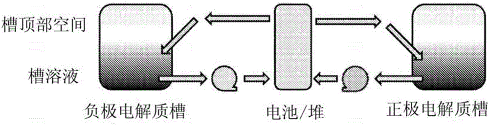
[0090] Redox flow battery cells without integrated additional cells According to Example 1.3, image 3 Assemble as described in . Titanium dicatecholate monopyrogallate (Ti(cat) 2 (gal) 2- ) and ferrocyanide (Fe(CN) 6 4- ) metal-ligand coordination compounds are used as active materials for the negative electrode electrolyte and the positive electrode electrolyte, respectively. Prepare the active material with a concentration of 1.5M, put it into a separate storage container, spray it with argon for 20 minutes, and flow it through a 25cm 2 carbon paper electrodes and Na + Form of NAFION TM Flow battery cells assembled with cation-selective membranes (50 μm thick). The battery was initially charged from 0 to 50% state of charge and OCV measurements were collected. Then, at 200mA / cm 2 Charge / discharge cycles were collected by sweeping the SOC of the battery from 20%-80% at a curre...
PUM
 Abstract
Description
Claims
Application Information
 - R&D
- Intellectual Property
- Life Sciences
- Materials
- Tech Scout
- Unparalleled Data Quality
- Higher Quality Content
- 60% Fewer Hallucinations
Browse by: Latest US Patents, China's latest patents, Technical Efficacy Thesaurus, Application Domain, Technology Topic, Popular Technical Reports.
© 2025 PatSnap. All rights reserved.Legal|Privacy policy|Modern Slavery Act Transparency Statement|Sitemap|About US| Contact US: help@patsnap.com