Long-distance high-speed safe connecting rod

A long-distance, connecting rod technology, applied in the driving device of metal rolling mill, metal processing equipment, metal rolling, etc., can solve the problems of accelerated safety pin wear, hexagonal bolt breakage, gland bolt loosening, etc., to reduce The effect of downtime, economic loss and labor intensity reduction

Inactive Publication Date: 2016-08-17
ANGANG STEEL CO LTD
View PDF6 Cites 0 Cited by
  • Summary
  • Abstract
  • Description
  • Claims
  • Application Information

AI Technical Summary

Problems solved by technology

[0003] 1) Both ends of the high-speed connecting rod are drum-shaped tooth joints. The drum-shaped teeth have tooth side clearance and tooth top clearance. Vibration during high-speed operation will easily cause the drum-shaped tooth joint gland bolts to loosen, and the grease will be thrown out. Exacerbated tooth joint wear
[0004] 2) Since the motor is far away from the reducer, the high-speed connecting rod has high requirements on the neutrality between the motor and the reducer, and installation errors may easily lead to vibration and axial serial movement of the high-speed connecting rod, resulting in impact deceleration of the high-speed connecting rod The shaft heads of motors and motors increase the frequency of motor and reducer failures
[0005] 3) The boss flange structure of the safety coupling is split and connected by hexagon socket bolts. Since the original design safety coupling internal bearings generally use double-row tapered bearings, axial force will be generated during use, plus 1 ), 2) due to the influence of the reasons, it is easy to cause the hexagonal bolts to break due to vibration
Once the bolt breaks, there will be gaps in the flange of the safety coupling, which will accelerate the wear of the safety pin or accelerate the fatigue of the safety pin to break, resulting in frequent accidents of the safety coupling

Method used


Image

  • Long-distance high-speed safe connecting rod

Examples


Embodiment Construction

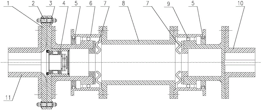
[0013] The specific embodiment of the present invention will be further described below in conjunction with accompanying drawing:

[0014] A long-distance high-speed safety connecting rod, which improves the structure of the drum-shaped tooth joint, cancels the original drum-shaped tooth joint and improves it into a ball coupling structure. Increase the inclination angle of the joints, reduce the neutral requirements for the motor and the reducer; improve the takeover gland and the sealing structure, change the original O-ring sealing structure to a Y-shaped lip seal, and improve the sealing ring's impact on the field transmission and swing angle. Adaptability, improve the sealing effect; improve the structure of the safety coupling, change the boss sleeve flange and the boss shaft flange into an integral structure, enhance the overall strength of the safety coupling, and at the same time make the safety coupling The original double-row tapered bearing inside the device is imp...


PUM


Abstract

The invention relates to a long-distance high-speed safe connecting rod, and belongs to the field of mechanical drive and control. The long-distance high-speed safe connecting rod comprises a boss shaft flange, safety pins, a boss sleeve flange, a deep groove ball bearing, a Y-shaped seal, a first ball coupling, disc springs, a rigid connecting rod and a second ball coupling. The long-distance high-speed safe connecting rod is characterized in that the outer diameter of a boss shaft of the boss shaft flange is connected with the inner diameter of the deep groove ball bearing in an interference fit mode, and the inner diameter of a boss sleeve of the boss sleeve flange is connected with the outer diameter of the deep groove ball bearing in an interference fit mode; the safety pins are mounted in pin holes of the boss shaft flange and pin holes of the boss sleeve flange. The defects of original long-distance high-speed connecting rods are effectively overcome through improvement of the structure and the connecting process of the high-speed safe connecting rod. By means of the long-distance high-speed safe connecting rod, the equipment accident rate can be effectively lowered, the spare part cost is reduced, great economic loss caused by accidents is reduced, the labor intensity of workers is lowered, shutdown time is reduced by average 30 days every year, and production efficiency is improved.

Description

technical field [0001] The invention relates to the field of mechanical transmission and control, in particular to a long-distance high-speed safety connecting rod device for the main rolling mill of a continuous rolling mill. Background technique [0002] The high-speed safety connecting rod is one of the main equipment of the main rolling mill of the continuous rolling mill, which is used to connect the main motor and the main reducer, transmit power and play the role of overload protection. At present, both ends of the common safety connecting rod are drum-shaped tooth joints, one end is installed on the shaft head of the motor, the other end is installed on the shaft head of the reducer, and the middle part is a rigid connecting rod and a safety coupling. The safety coupling is composed of a boss sleeve flange, a boss shaft flange, 2 sets of bearings, and 2 sets of safety pins. The outer diameter of the boss shaft of the flange matches the inner ring of the bearing, and...

Claims


Application Information

Patent Timeline
Patent Type & Authority Applications(China)
IPC IPC(8): B21B35/14
Inventor 胡小冬陈勇胡斌李道刚董芬吴宇新李应雄翟利平王茹洪汛
Owner ANGANG STEEL CO LTD
Why Eureka
Try Eureka