Continuous casting machine

A casting machine and machine head technology, applied in casting equipment, equipment for feeding molten metal into molds, manufacturing tools, etc., can solve problems such as water leakage, mold damage, motor burnout, etc., to protect the mold and transmission system, reduce Maintenance costs and the effect of ensuring safe production

Inactive Publication Date: 2016-08-17
宁夏铸源机械制造有限公司
View PDF10 Cites 4 Cited by
  • Summary
  • Abstract
  • Description
  • Claims
  • Application Information

AI Technical Summary

Problems solved by technology

[0002] In the metal smelting industry, after the molten metal is cooled and solidified, how to make it into pieces according to the needs of customers has become a big problem. In the past, most of the smelted molten metals were poured into a large cooling pool In the process, after waiting for it to solidify, the large alloy is broken by manpower. This primitive method has many disadvantages. The use of labor costs a lot. During the crushing process, the splashed debris is easy to hurt people and is very dangerous. , there will be at least 20% of the broken foam in the broken products. When these broken foams are sold, the price is far lower than that of qualified products, causing losses
[0003] The ferroalloy casting machine proposed in the comparative document (Application No. 200810230825.7) lacks a release agent spraying process, which makes it difficult for the alloy cast into the mold to be separated from the mold. The demoulding of the mold bar, because of the lack of mold release agent, its demoulding efficiency is bound to be low, and the mold is turned over for a long time, causing serious wear to the positioning shaft, and the mold knocks the demoulding bar for a long time, which is also very easy to cause mold damage. The buffer of the reducer and the coupling can easily cause the motor to burn out, and the replacement and maintenance are time-consuming and laborious. In summary, the ferroalloy casting machine disclosed in the comparative document has great defects

Method used


Image

  • Continuous casting machine
  • Continuous casting machine
  • Continuous casting machine

Examples


Embodiment

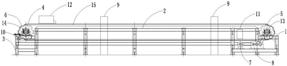
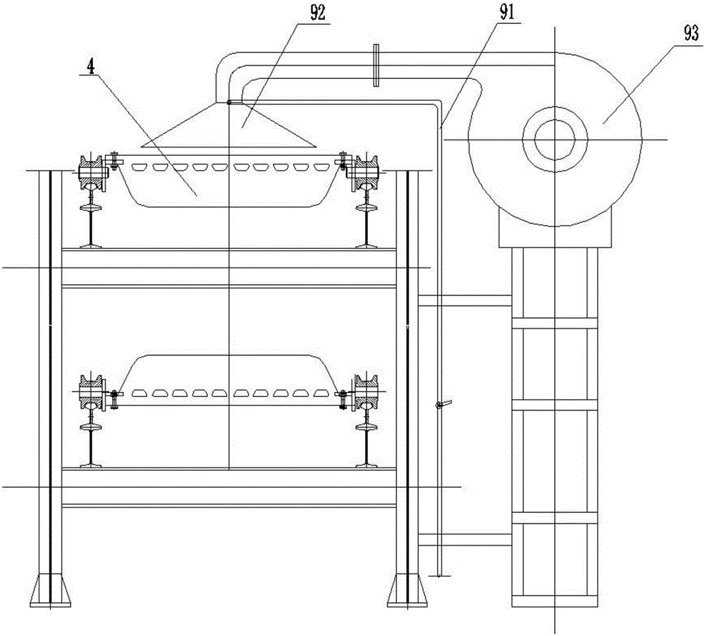
[0020] After starting up, the motor rotates and transmits to the reducer. The reducer drives the drive shaft of the machine head through the coupling. The drive shaft of the machine head drives the drive sprocket of the machine head. With the closed transmission structure, the mold fixedly installed on the transmission chain also runs accordingly. The mold first passes through the release agent spraying device at the rear of the tailstock, sprays a layer of release agent on the surface of the mold, and then transfers to the bottom of the casting port. The molten steel in the ladle is buffered by the casting port, flows evenly into the mold that has been sprayed with release agent, and then slowly runs towards the head frame, passing through two cooling devices during the process, and the cooling water in the cooling device passes through the axial flow fan The blown gas is evenly sprayed on the mold and the alloy ingot in the mold to realize the rapid cooling of the mold and th...


PUM


Abstract

The invention provides a continuous casting machine, and belongs to metallurgical equipment. The continuous casting machine comprises a machine head frame, a machine body frame, a machine tail frame, a die, machine head transmission chain wheels, a machine head transmission main shaft, a machine tail transmission chain wheel, a machine tail transmission shaft, a motor, a speed reducer, a transmission chain, cooling devices, a die releasing agent spraying device, a die releasing device and a casting port, wherein the machine head frame, the machine body frame and the machine tail frame are all of rectangular steel frame structures and are sequentially integrally fixedly connected; bearing blocks which are assembled to the machine head transmission main shaft are mounted at two sides of the machine head frame; the machine head transmission chain wheels are mounted at two ends of the machine head transmission main shaft. The continuous casting machine is simple in structure; all components can be independently dismounted and replaced, so that the convenience of maintenance is ensued, a plurality of problems caused by manual breaking can be completely solved, and as a result, huge economic benefits can be brought to metallurgical enterprises.

Description

Technical field: [0001] The invention belongs to a metallurgical equipment, and the name of the invention is a continuous casting machine. Background technique: [0002] In the metal smelting industry, after the molten metal is cooled and solidified, how to make it into pieces according to the needs of customers has become a big problem. In the past, most of the smelted molten metals were poured into a large cooling pool In the process, after waiting for it to solidify, the large alloy is broken by manpower. This primitive method has many disadvantages. The use of labor costs a lot. During the crushing process, the splashed debris is easy to hurt people and is very dangerous. , There will be at least 20% of the broken foam in the broken product. When these broken foam are sold, the price is far lower than that of qualified products, causing losses. [0003] The ferroalloy casting machine proposed in the comparative document (Application No. 200810230825.7) lacks a release a...

Claims


Application Information

Patent Timeline
Patent Type & Authority Applications(China)
IPC IPC(8): B22D35/04B22D29/04B22D30/00
CPCB22D35/04B22D29/04B22D30/00
Inventor 孟要谦孟洋
Owner 宁夏铸源机械制造有限公司
Why Eureka
Try Eureka