Lamp tube coding device and coding method

A lamp and coding machine technology, which is applied in the directions of typewriter, transportation and packaging, conveyor objects, etc., can solve the problem that the coding position of the lamp cannot be guaranteed to be uniform and fixed, so as to improve the leveling efficiency, facilitate control and production. Efficient effect

Active Publication Date: 2016-08-17
SICHUAN SUNRAIN SIGN & DISPLAY SYST
View PDF11 Cites 2 Cited by
  • Summary
  • Abstract
  • Description
  • Claims
  • Application Information

AI Technical Summary

Problems solved by technology

[0004] The purpose of the present invention is to provide a lamp coding device and a coding method in view of the deficiency that the coding position of the lamp tube cannot be guaranteed to be uniform and fixed in the prior art

Method used


Image

  • Lamp tube coding device and coding method
  • Lamp tube coding device and coding method
  • Lamp tube coding device and coding method

Examples


Embodiment 1

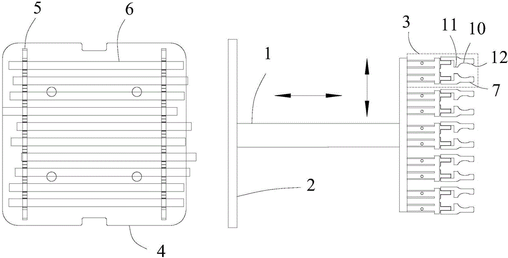
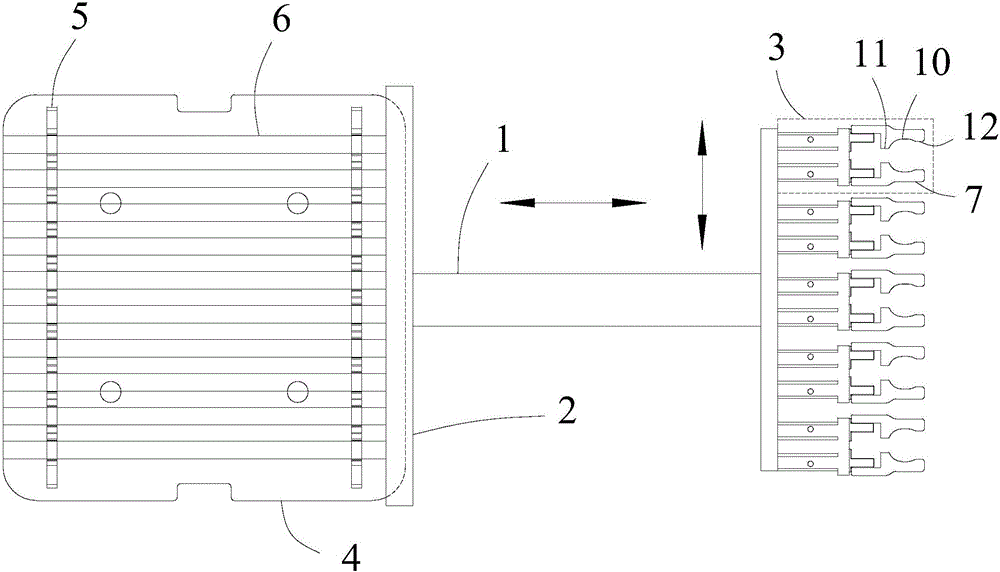
[0066] Such as figure 1 , a lamp coding device, comprising a lamp support part 4, a coding machine 8, a flattening part, and a lamp grabbing part, the lamp support part 4 is provided with two for placing the lamp 6 clamping pieces 5, two clamping pieces 5 are arranged oppositely on the lamp tube supporting part 4, the flattening part includes a moving part 1 and a flat plate 2 connected to one end thereof, and the flat plate 2 is opposite to the lamp tube 6. The axis is vertically arranged. The moving part 1 drives the flat plate 2 to perform reciprocating axial movement and lateral movement along the direction of the arrow in the figure. The other end of the moving part 1 is connected to the lamp grabbing part. Contains ten lamp tube clamps 3, two said lamp tube clamps 3 are arranged as a group facing each other. On a straight line, each of the lamp clamps 3 includes two opposite clamping arms 7, the size and shape of the two clamping arms 7 are the same, and the two clampin...

Embodiment 2

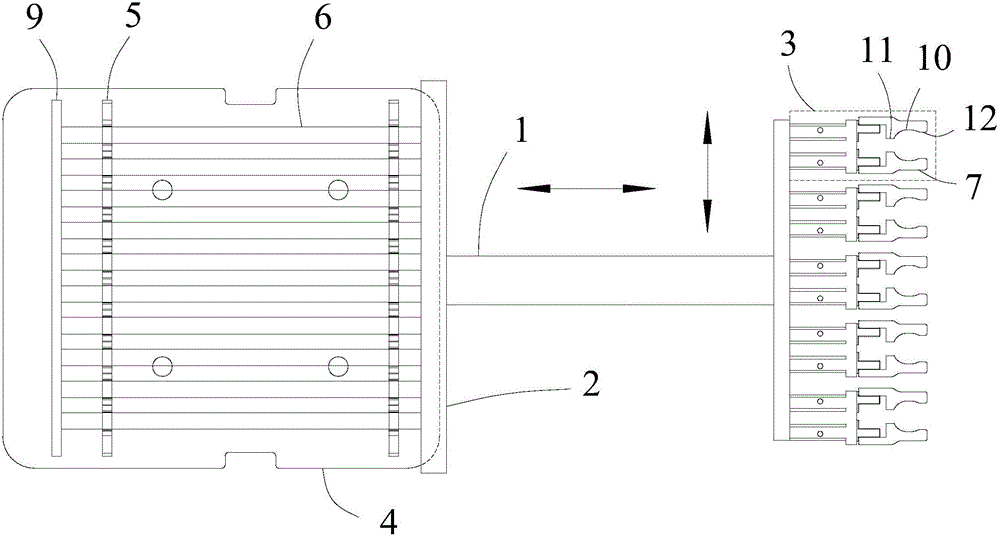
[0069] Specific as image 3 , a light tube coding device, the difference from Embodiment 1 is that a baffle 9 is provided on the outside of the clamping member on the opposite side of the flat plate, and the baffle 9 is perpendicular to the light tube, The height of the baffle plate 9 is higher than the height of the lamp tube 6, and the length matches the clamping member 5. In the initial state, several of the lamp tubes 6 are not aligned. When the moving part 1 drives the plate 2. After the lamp tube 6 is pushed to move for a certain distance, the baffle plate 9 restricts the lamp tube 6 from continuing to move. At this time, both ends of the lamp tube 6 are flush to prevent the pushed end from falling due to the push. At the same time, it can also reduce the error caused by the inertia when pushing to stop, effectively save the pushing distance, improve the leveling efficiency, save costs, increase safety, and then improve the production efficiency of the entire assembly li...

Embodiment 3

[0072] A coding method for a lamp coding device, comprising using a lamp coding device as in embodiment 1 or 2, the method of use comprising the following steps:

[0073] Step 1. Use the moving part 1 to drive the flat plate 2 to move to the side of the end of the light tube, perpendicular to the light tubes 6 , and the position of the flat plate 2 is compatible with all the light tubes 6 .

[0074] Step 2: Use the moving part 1 to drive the flat plate 2 to push along the axial direction of the lamp tubes 6, and stop after pushing a suitable distance, so that the ends of all the lamp tubes 6 are aligned.

[0075] Step 3: grab the lamp tube 6 with the lamp tube chuck 3 on the lamp tube grabbing part.

[0076] Step 4: Use the lamp tube chuck 3 on the lamp tube grabbing part to move to the coding machine 8 for coding respectively until all the lamp tubes 6 are coded.

[0077] After all the lamp tubes are flattened, grab and move to the coding machine 8 to code, ensuring that the...


PUM


Abstract

The invention discloses a lamp tube coding device and a coding method. The lamp tube coding device comprises lamp tube supporting components, a leveling component, a lamp tube grabbing component and a coding machine. A plurality of clamping pieces used for containing lamp tubes are arranged on each lamp tube supporting component. The leveling component comprises a flat plate and a movement component which can drive the flat plate to move. The lamp tube grabbing component comprises at least one lamp tube chuck. Each lamp tube chuck comprises two openable clamping arms. The coding machine is used for coding each lamp tube. The coding method of the lamp tube coding device comprises the steps that the lamp tubes placed on the lamp tube supporting components are leveled by means of the leveling component, and the lamp tubes are grabbed by the lamp tube grabbing component and moved to the position of the coding machine so as to be coded. The lamp tube coding device is simple in structure, the space is effectively saved, the coding efficiency is high, the consistency is good, and the cost is effectively reduced; and by the adoption of the method, coding positions can be effectively controlled, the coding efficiency is improved, and the consistency of the coding positions is also improved.

Description

technical field [0001] The invention relates to a lamp production line, in particular to a coding device and a coding method for a lamp tube. Background technique [0002] In the production of lamp tubes, several lamp tubes and various types of lamp tubes will be produced in batches. In order to facilitate classification management, product traceability and brand identification, it is necessary to code each lamp tube and print the brand and model , production date and other information, since each lamp tube needs to be coded, the amount of information is large, and at the same time, for the sake of beauty and easy management, the position of the code needs to be kept fixed and unified. [0003] In the prior art, due to manually grabbing the lamp tubes for coding, the number of grabs each time is small, and the efficiency is not high. At the same time, because the position of each grab is difficult to fix, the position of coding is mainly controlled by experience and cannot b...

Claims


Application Information

Patent Timeline
Patent Type & Authority Applications(China)
IPC IPC(8): B41J3/407B65G47/82B65G47/90
CPCB41J3/407B65G47/82B65G47/90B65G2201/0276
Inventor 杨益见刘刚何龙付正军
Owner SICHUAN SUNRAIN SIGN & DISPLAY SYST
Why Eureka
Try Eureka