Heater structure for heating and activating micro-miniature self-heating air suction agents and method for manufacturing heater structure

A heat-activated, micro-miniature technology, applied in the direction of microstructure technology, microstructure devices, electrical components, etc., can solve the problems of wire insulation layer rupture, electrode contact point melting, getter failure, etc., to achieve simple and easy control , good insulation properties, good consistency effect

Active Publication Date: 2016-08-17
XINFOO SENSOR TECH CO LTD
View PDF4 Cites 2 Cited by
  • Summary
  • Abstract
  • Description
  • Claims
  • Application Information

AI Technical Summary

Problems solved by technology

If the contact is poor, the contact resistance is too large or even larger than the resistance of the wire heater, which may cause the electrode contact point to melt or fuse due to overheating
At the same time, the resistance of the contact electrode will have a deviation of several milliohms or tens of milliohms, and the overall resistance deviation for the activation of the entire wire heater is tens of percent. When the wire heater is energized and activated, the same heating Current, due to the deviation of resistance, the deviation of its heating power may be a multiplied deviation
In the same way, the resistance difference of the metal wire as a heating resistor is very small because the overall resistance is only tens to hundreds of milliohms, so the resistance value deviation of several milliohms to more than ten milliohms may produce low heating power. Large deviation, the existence of this type of resistance deviation seriously

Method used


Image

  • Heater structure for heating and activating micro-miniature self-heating air suction agents and method for manufacturing heater structure
  • Heater structure for heating and activating micro-miniature self-heating air suction agents and method for manufacturing heater structure

Examples


Example Embodiment

[0027] In order to make the objectives, technical solutions, and advantages of the embodiments of the present invention clearer, the technical solutions in the embodiments of the present invention will be described clearly and completely in conjunction with the accompanying drawings in the embodiments of the present invention. Based on the embodiments of the present invention, all other embodiments obtained by those of ordinary skill in the art without creative work shall fall within the protection scope of the present invention.
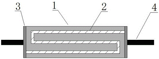
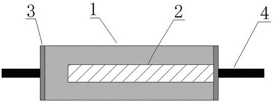
[0028] In the prior art, such as small-volume self-heating getters used in vacuum packaging, the usual problem is that the resistance of the metal wire as a heater cannot be processed to be very large; The power required for electric heating to reach the ideal activation temperature of the getter material, and the current required for activation is relatively large (3A-7A). Such a large current puts forward higher design requirements for the design of ...


PUM


Abstract

The invention relates to the field of vacuum packaging technologies for MEMS (micro-mechanical systems) sensors, in particular to a heater structure for heating and activating micro-miniature self-heating air suction agents and a method for manufacturing the heater structure. The heater structure comprises a ceramic body, metal slurry, metal coatings and metal leading wires. The inside of the ceramic body is divided into a plurality of layers, the metal slurry wraps each layer, metal slurry layers are communicated with one another in the up-down directions, the metal slurry on two end surfaces of the ceramic body is reserved to be exposed, the metal coatings are formed on two end surfaces of the ceramic body by means of chemical plating or electroplating, and the metal leading wires of heating electrodes are welded on the two end surfaces of the ceramic body after the metal coatings are formed. The heater structure and the method have the advantages that resistance of the metal slurry layers is controlled, so that the consistency of resistance values of different devices can be guaranteed; whether heating and activating temperatures reach ideal activating temperatures of air suction materials or not can be monitored by special circuits in an online manner and can be controlled, accordingly, the activated air suction agents can be assuredly in the optimal activated states, and the activated states of the air suction agents are consistent and stable on a large scale.

Description

technical field [0001] The invention relates to the technical field of vacuum packaging of MEMS sensors, in particular to a thermon structure and a manufacturing method for heating and activating a miniature self-heating getter. Background technique [0002] Sensors with MEMS structures such as infrared thermal imaging and THz require high-vacuum, constant temperature, and small-volume packaging. The traditional metal shell packaging and ceramic shell packaging process realizes the packaging of special sensor chips. In order to meet the special working environment conditions and packaging requirements of high vacuum, constant temperature, and long life, it is usually used to install a getter in the package shell to maintain the sensor chip. Vacuum required for normal operation, thus increasing the life of the sensor. When the getter is used, it needs to be heated to a certain temperature to activate the getter properties of the material, and then vacuum-packed to maintain t...

Claims


Application Information

Patent Timeline
IPC IPC(8): B81B7/00
CPCB81B7/0032
Inventor 赵照
Owner XINFOO SENSOR TECH CO LTD
Why Eureka
Try Eureka