Sponge city construction groundwater recharge well and rapid well formation method thereof

A technology of sponge city and recharge well, which is applied in construction, waterway system, sewage removal, etc., can solve the problems of high cost, long time, complicated construction, etc., and achieve the effect of convenient backfill and convenient processing.

Inactive Publication Date: 2016-08-17
WATER RESOURCES RES INST OF SHANDONG PROVINCE
View PDF7 Cites 10 Cited by
  • Summary
  • Abstract
  • Description
  • Claims
  • Application Information

AI Technical Summary

Problems solved by technology

[0003] Aiming at the problems of complex construction, high cost, and long time in the existing groundwater infiltration facilities in the construction of sponge cities, the present invention provides a groundwater recharge well for sponge city construction, which can avoid the occurrence of the above problems

Method used


Image

  • Sponge city construction groundwater recharge well and rapid well formation method thereof
  • Sponge city construction groundwater recharge well and rapid well formation method thereof
  • Sponge city construction groundwater recharge well and rapid well formation method thereof

Examples


no. 1 example

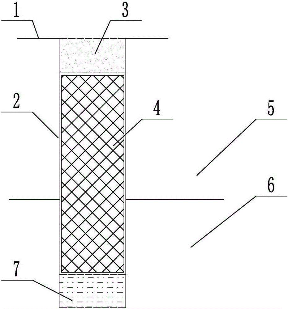
[0033] Such as figure 1 and figure 2 As shown, the sponge city construction groundwater recharge well includes a borehole 2, and the borehole 2 can be arranged on the roadside, lawn, parking lot, below the permeable road surface, in a community or in a unit courtyard, etc., and can also be used in infiltration ponds, For internal use in seepage wells, wet ponds, rainwater wetlands, etc.

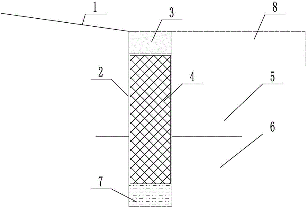
[0034] Such as figure 2 Said, the borehole 2 is set on the road surface 1 close to the lawn 8 or in the lawn 8 . The road surface 1 can be a road surface with a common cross slope of 1.5%-2% in urban construction, and can be further optimized to a road surface 1 with a slope of 3%-5%, without changing the original road structure. When precipitation occurs, Rain (or snowmelt) water will quickly flow into the borehole 2 along the slightly inclined road surface 1 .

[0035] After the borehole 2 cuts through the aquifer 5 to the water-bearing sand layer 6 to form a well, first lay a 20-30cm...

no. 2 example

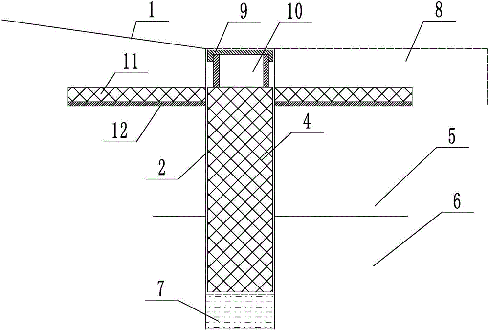
[0043] Such as image 3 and Figure 4 As shown, the difference from the first embodiment is that a wellhead connection device is added, and the wellhead connection device includes a reinjection well joint 10 , a water-permeable reinjection well cover 9 , a sponge strip 11 and a connecting channel 12 . A recharge well joint 10 is arranged on the top of the hard sponge 4, and a permeable recharge well cover 9 is screw-mounted on the recharge well joint 10, and the well cover is slightly higher than the ground. This design can avoid the problem of initial rainwater pollution. , the clean rainwater in the later stage can infiltrate through the permeable recharge manhole cover 9 with osmosis.

[0044] One side of the hard sponge 4 is provided with a connecting channel 12, such as Figure 4 Said, several connecting passages 12 are provided on the periphery of the hard sponge, and the connecting passages 12 can be U-shaped grooves, arc-shaped grooves, or other grooves with communic...

no. 3 example

[0047] Such as Figure 5 As shown, the difference from the first embodiment is that a curbstone 13 is arranged above the hard sponge 4, and an L-shaped channel for rainwater diversion is arranged in the curbstone.

[0048] A more optimal design is provided with a sand filter layer between the hard sponge and the roadside stone.

[0049] This design can be retrofitted without destroying the existing roads, with low cost and good rainwater infiltration.


PUM


Abstract

The invention provides a sponge city construction groundwater recharge well and relates to the technical field of drainage facility. The sponge city construction groundwater recharge well comprises a drill hole which penetrates an aquitard and a water-bearing sand layer, wherein the drill hole is internally provided with a rapid sponge; a gravel bed anti-filtration layer is arranged between the rigid sponge and the bottom of the drill hole; the outer layer of the rigid sponge is coated with a geotechnical fabric; the part, which is 20-30cmm away from the ground 1, at the top of the rigid sponge is provided with a sand layer anti-filtation layer which is flush with the road surface. The invention also provides a rapid well formation method of the recharge well. A drill machine is used for drilling holes; the sand gravel anti-filtration layer is paved at the bottom of the drill hole and is provided with the rigid sponge; the outer side of the rigid sponge is wrapped with a geotechnical fabric; then the sand layer anti-filtration layer is paved on the geotechnical fabric and is flush with the road surface, so that the groundwater recharge well is formed. The sponge city construction groundwater recharge well is capable of solving the problems of complex construction, high cost, long time and the like in groundwater infiltration facility during existing sponge city construction.

Description

technical field [0001] The invention relates to the technical field of drainage facilities, in particular to a groundwater recharge well for construction of a sponge city and a method for rapidly forming the well. Background technique [0002] At present, in the process of sponge city construction, a part of the rainwater is confluenced, purified and then infiltrated through facilities such as permeable pavements, infiltration ponds, infiltration wells, wet ponds, and rainwater wetlands. Therefore, the infiltration effect of the permeable layer is not good. Large-caliber machine drilling and machine-dug wells are usually used to backfill the sand and gravel filter layer for infiltration wells. The construction is complex, costly, takes up a lot of land, and takes a relatively long time. Contents of the invention [0003] Aiming at the problems of complex construction, high cost, and long time in the existing groundwater infiltration facilities in the construction of sponge...

Claims


Application Information

Patent Timeline
Patent Type & Authority Applications(China)
IPC IPC(8): E03F1/00
CPCE03F1/002
Inventor 张保祥张鹏云徐运海张超黄继文
Owner WATER RESOURCES RES INST OF SHANDONG PROVINCE
Why Eureka
Try Eureka