Vertical-axis shaft water flow power generation device and testing system

A technology of water current power generation and test system, which is applied in hydroelectric power generation, measuring devices, fluid dynamics tests, etc., can solve problems such as high cost, difficult installation, underwater sealing, anti-corrosion, difficult installation and maintenance, etc., and achieves light weight and structure The effect of simplicity, protection and maintenance is simple

Inactive Publication Date: 2016-08-17
CHONGQING GEARBOX
View PDF9 Cites 3 Cited by
  • Summary
  • Abstract
  • Description
  • Claims
  • Application Information

AI Technical Summary

Problems solved by technology

The "vertical axis tidal current power generation device" disclosed in the patent document with the application number 201020621184 is mainly characterized by the double-end support structure of the blade shaft. The biggest defect of this structure is to ensure the coaxiality of the bearings at both ends of the impeller shaft. And to play a supporting role, the rigidity of the impeller frame must be large enough. The weight of this frame is bound to account for nearly half of the weight of the entire system, and the installation is also difficult.
In short, the underwater sealing, anti-corrosion, installation and maintenance of the above typical vertical axis power generation devices are very difficult and costly

Method used


Image

  • Vertical-axis shaft water flow power generation device and testing system
  • Vertical-axis shaft water flow power generation device and testing system
  • Vertical-axis shaft water flow power generation device and testing system

Examples


Embodiment 1

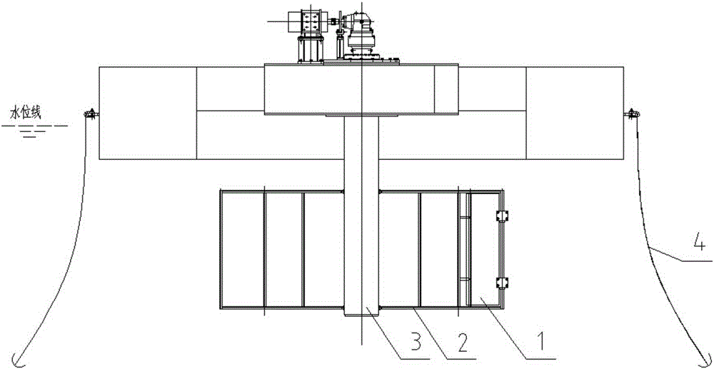
[0027] Example 1, such as Figure 1-3 As shown: the vertical axis hydroelectric power generation device of the present invention is composed of impeller, anchor chain 4, floating support platform 5, main platform 6, slewing support bearing 7, connecting flange 8, universal coupling 9, gear coupling, Speed ​​increaser 11, brake 12, generator 13, first torque speed sensor 14, support beam 15 and other components.

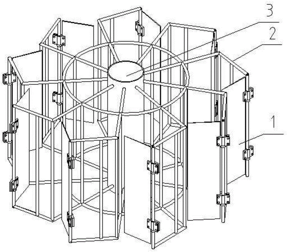
[0028] The present invention is further optimized and improved on the basis of 201420550695.6. The impeller includes a blade 1, a blade frame 2 and an impeller main shaft 3. The impeller main shaft 3 is a hollow shaft. There are nine blade frames 2. The blade frame 2 is an L-shaped frame. 2. One end is welded to the impeller main shaft 3 and radially distributed evenly along the impeller main shaft 3. All blade holders 2 rotate in the same direction. The upper and lower ends of all blade holders 2 are respectively connected and fixed by circular or regular hexagonal s...

Embodiment 2

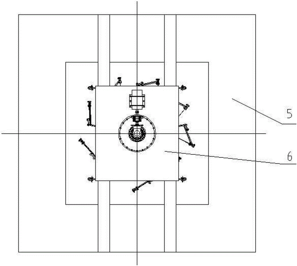
[0032] Embodiment 2, test system

[0033] Such as Figure 4-5 , comprising a vertical-axis hydroelectric power generation device, which is placed in a pool, the vertical-axis hydroelectric power generation device is the same as in Embodiment 1, the difference is that the support beam 15 is not fixed on the floating support platform 5, and in the impeller main shaft 3 The second torque speed sensor is installed, and the first torque speed sensor 14 is arranged on the output shaft of the speed increaser 11 .

[0034]The floating support platforms 5 on both sides of the main platform 6 are provided with pool guide rails 20 respectively, and two support beams 15 are arranged symmetrically on both sides of the main platform 6 respectively, and the support beams 15 are extended to roll or slidingly connect with the pool guide rails 20 on both sides. Specifically, the wheels 21 are installed below the end of the support beam 15, the wheel grooves are limited in the pool track 20, an...


PUM


Abstract

The invention discloses a vertical-axis shaft water flow power generation device and a testing system. The vertical-axis shaft water flow power generation device comprises an impeller, a floating supporting platform, a speed increaser and a power generator, wherein the impeller is composed of blades, blade frames and an impeller spindle; the blade frames are welded with the impeller spindle and are uniformly distributed along the impeller spindle radioactively in an equal part; the blades are hinged to the corresponding blade frames through corresponding hinges; the power generator is installed on the floating supporting platform; and an input shaft of the power generator is connected with an output shaft of the speed increaser. The vertical-axis shaft water flow power generation device is characterized in that a rotary support bearing is installed on the floating supporting platform; and the upper end of the impeller spindle is fixed in the rotary support bearing, sequentially passes through a universal coupling and a gear coupling and is connected with an input shaft of the speed increaser. The vertical-axis shaft water flow power generation device is light in weight, convenient in installation, better in starting and braking characteristics, strong in adaptation to environment and high in power generation efficiency.

Description

technical field [0001] The invention relates to the field of power generation devices, in particular to a vertical axis water current power generation device and a testing system thereof. Background technique [0002] The world's demand for energy is growing rapidly and the total amount is huge, and the supply capacity is becoming increasingly tight. The development of green and pollution-free new energy industries and the promotion of low-carbon economy have reached a consensus in countries around the world. At present, among renewable energy sources, wind energy and solar energy have been widely developed, but their conversion efficiency is low; although river hydropower stations can be regarded as effective use of renewable water energy, the investment is large and poses a threat to the ecological environment and geology . The development of new environment-friendly hydroelectric power generation has become an inevitable trend, including river current energy, ocean curr...

Claims


Application Information

Patent Timeline
Patent Type & Authority Applications(China)
IPC IPC(8): F03B13/00F03B3/14B63B35/44G01M10/00
CPCB63B35/44B63B2035/4466F03B3/14F03B13/00F05B2220/706G01M10/00Y02E10/20
Inventor 杨超阙洪军吕和生高德芳周飞鸿王辉全
Owner CHONGQING GEARBOX
Why Eureka
Try Eureka