[0061] In order to further illustrate the technical solution of the present invention, in conjunction with the accompanying drawings, the specific implementation of the present invention is as follows:
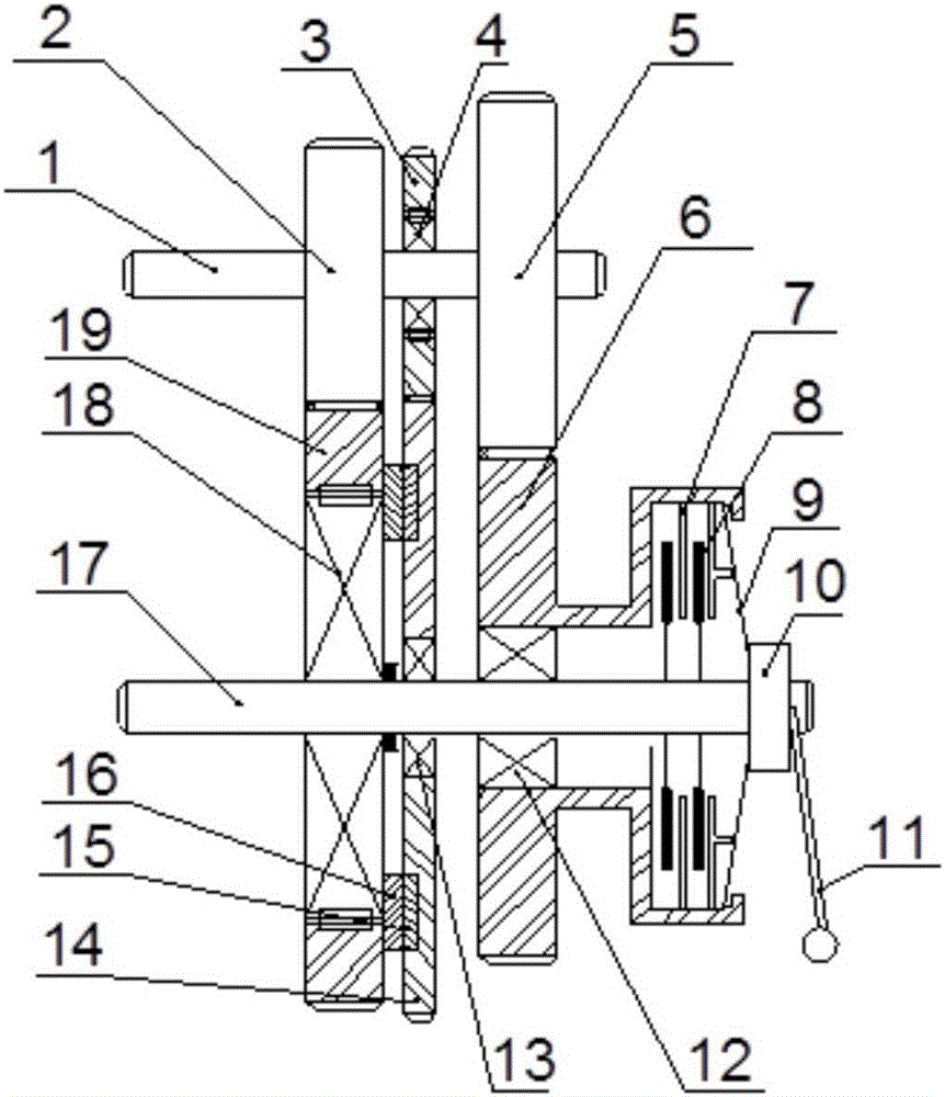
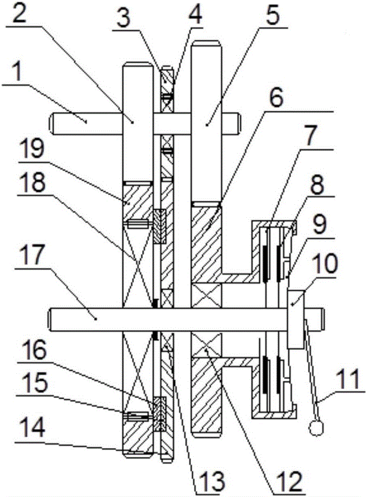
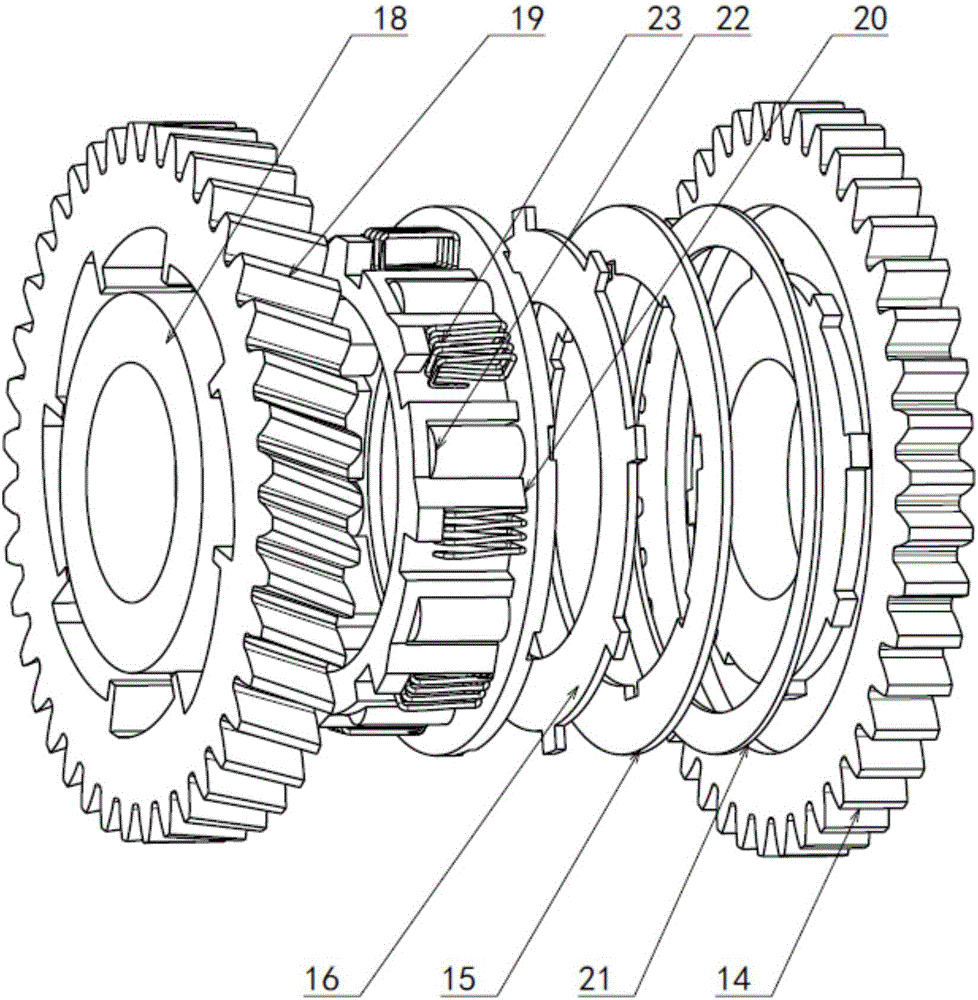
[0062] In a nutshell, the gearbox of the present invention is mainly composed of three pairs of gears, two overrunning clutches and a disc clutch, one pair of the three pairs of gears can control the overrunning clutch on the output shaft, and the other two pairs of different transmission The ratio gear pair is two gears, and the transmission ratio of the intermediate gear pair where the overrunning clutch is controlled is greater than the transmission ratio of the first gear pair.
[0063] like figure 1 , figure 2 and Figure 8 As shown, the present invention discloses a non-power interruption shift gearbox for an electric vehicle, which is composed of an input shaft 1, a first gear pair mechanism, a second gear pair mechanism, a plate clutch, an output shaft 17, and a shift control mechanism.
[0064] The first-gear gear pair mechanism is composed of a first-gear driving gear 2 fixedly connected to the input shaft 1 and a first-gear passive gear 19 mounted on the output shaft 17 to form meshing transmission connection. The second-speed gear pair mechanism is composed of a second-speed driving gear 5 fixedly connected to the input shaft 1 and a second-speed driven gear 6 installed on the output shaft 17 through the first bearing 12 in meshing transmission connection. The shift control mechanism is located between the gear pair mechanism of the first gear and the gear pair mechanism of the second gear.
[0065] like figure 1 , figure 2 As shown, the shift control mechanism includes a first gear overrunning clutch Figure 4 , control overrunning clutch Figure 5 , the control gear pair mechanism, the roller control mechanism of the first gear overrunning clutch image 3 , Figure 7;
[0066] like figure 1 , figure 2 As shown, the first gear overrunning clutch Figure 4 Installed in the first-gear driven gear 19, the first-gear overrunning clutch inner ring 18 is fixedly connected on the output shaft 17, and the first-gear overrunning clutch outer ring and the first-gear driven gear 19 have an integrated structure; the control overrunning clutch Figure 5 Installed in the first control gear 3, the inner ring of the control overrunning clutch is fixedly connected to the input shaft 1, and the outer ring of the control overrunning clutch is integrated with the first control gear 3;
[0067] The control gear pair mechanism is composed of a first control gear 3 mounted on the input shaft 1 and a second control gear 14 mounted on the output shaft 17 through bearings in meshing transmission connection;
[0068] The transmission ratio of the control gear to the mechanism is greater than the transmission ratio of the first gear gear to the mechanism;
[0069] The roller toggling mechanism for toggling the rollers in the roller control mechanism of the first-speed overrunning clutch has two implementations, which are respectively the roller cage 20 or the roller fork frame 26;
[0070] like image 3 As shown, option one: the roller control mechanism of the first-speed overrunning clutch is composed of a roller cage 20, a preload spring A23, a control pressure plate 15, a wave spring 21, and a control friction plate 16.
[0071] The control friction plate 16 is fixed in the groove on the end surface of the roller cage 20 through the protrusion on the outer edge, and the wave spring 21 is installed in the annular groove on the end surface of the second control gear 14; the control pressure plate 15 is installed Between the control friction plate 16 and the wave spring 21, the wave spring 21 is axially preloaded, so that the control pressure plate 15 is closely attached to the control friction plate 16, and the control pressure plate 15 is fixed by the protrusion on the inner edge Rotate with the second control gear 14 in the annular groove on the end face of the second control gear 14;
[0072] A transmission without power interruption for an electric vehicle, wherein the first-gear overrunning clutch includes a first-gear passive gear 19, a first-gear overrunning clutch inner ring 18, a roller cage 20, a roller A22, and a preload spring A23;
[0073] like Figure 4 As shown, the inner surface of the first-gear driven gear 19 and the outer surface of the first-gear overrunning clutch inner ring 18 form a wedge-shaped space, and the roller cage 20 is sleeved on the first-gear overrunning clutch inner ring 18, and is located on the first-gear overrunning clutch inner ring. Between 18 and the first-speed driven gear 19, the rollers A22 are evenly distributed in the roller cage 20, and the rotation of the roller cage 20 can drive the wedge-shaped space between the first-speed overrunning clutch inner ring 18 and the first-speed driven gear 19. The rollers A22 move synchronously, the preload spring A23 is evenly distributed in the roller cage 20, one end of the preload spring A23 is in contact with the roller cage 20, and the other end is in contact with the protrusion on the inner surface of the first gear driven gear 19, The roller cage 20 pretensions the roller A22 at the end of the wedge-shaped space with a small space through the pretension spring A23.
[0074] like image 3 As shown, the outer peripheral surface of the roller cage 20 is provided with a raised limit block, the limit block is located on the left side of the installation place of the pre-tension spring A23, and the function of the limit block is that the roller cage When 20 rotates counterclockwise relative to the first-speed driven gear 19, the limit block interferes with the protrusion on the inner surface of the first-speed driven gear 19 after turning through a certain angle, so as to prevent the roller cage 20 from excessively pressing the preload spring A23 .
[0075] like Figure 7As shown, option two: the roller control mechanism of the first-speed overrunning clutch can also be composed of a roller shift fork frame 26, a preload spring A23, a control pressure plate 15, a wave spring 21, and a control friction plate 16.
[0076] The control friction plate 16 is fixed in the groove on the end surface of the roller shift fork frame 26 through the protrusion on the outer edge, and the wave spring 21 is installed in the annular groove on the end surface of the second control gear 14; the control pressure plate 15 Installed between the control friction plate 16 and the wave spring 21, the wave spring 21 is axially pre-tensioned, so that the control pressure plate 15 is closely attached to the control friction plate 16, and the control pressure plate 15 is engaged by the protrusion on the inner edge It is fixed in the annular groove on the end face of the second control gear 14 and rotates with the second control gear 14;
[0077] A transmission without power interruption for an electric vehicle, wherein the first-gear overrunning clutch includes a first-gear passive gear 19, a first-gear overrunning clutch inner ring 18, a roller fork frame 26, a roller A22 and a preload spring A23 ;
[0078] The inner surface of the first-gear passive gear 19 and the outer surface of the first-gear overrunning clutch inner ring 18 form a wedge-shaped space. Between the first-speed passive gear 19, the rollers A22 are evenly distributed in the wedge-shaped space, and the rotation of the roller fork frame 26 can move the rollers in the wedge-shaped space between the first-speed overrunning clutch inner ring 18 and the first-speed passive gear 19. A22 moves synchronously, the pretension spring A23 is evenly distributed in the wedge-shaped space, one end of the pretension spring A23 is in contact with the roller A22, and the other end is in contact with the protrusion on the inner surface of the first gear driven gear 19, and the pretension spring A23 pushes the roller A22 Preload at the end of the wedge with less space.
[0079] like Figure 7 As shown, the outer peripheral surface of the roller shift fork frame 26 is provided with a raised limit block, and the limit block is located on the left side of the installation place of the pre-tightening spring A23. The function of the limit block is that the roller shifts When the fork frame 26 rotates counterclockwise relative to the driven gear 19 of the first block, the limit block interferes with the protrusion on the inner surface of the driven gear 19 of the first block after turning over a certain angle, so as to prevent the fork of the roller shifting fork frame 26 from being excessive. Squeeze preload spring A23.
[0080] like Figure 5 , an electric vehicle without power interruption shift transmission, wherein the control overrunning clutch includes a first control gear 3, a control overrunning clutch inner ring 4, a roller B24 and a preload spring B25;
[0081] The inner surface of the first control gear 3 and the outer surface of the inner ring 4 of the control overrunning clutch form a wedge-shaped space, and the rollers B24 are evenly distributed in the wedge-shaped space, and are pre-tightened at the end of the wedge-shaped space by the pretension spring B25;
[0082] A transmission without power interruption for electric vehicles, wherein the plate clutch is composed of a clutch friction plate 7, a clutch pressure plate 8 and a thrust bearing 10;
[0083] When the disc clutch is installed on the input shaft 1, the second gear driving gear 5 is fixedly connected to the clutch friction plate 7, the clutch pressure plate 8 is fixedly connected to the input shaft 1, and the thrust bearing 10 is sleeved on the input shaft 1, and Slip and rotate on axis 1;
[0084] When the disc clutch is installed on the output shaft 17, the second gear driven gear 6 is fixedly connected with the clutch friction plate 7, the clutch pressure plate 8 is fixedly connected with the output shaft 17, the thrust bearing 10 is sleeved on the output shaft 17, and Slip rotation on the shaft 17.
[0085] The plate clutch is a dry multi-plate clutch or a dry single-plate clutch;
[0086] The invention also discloses a shifting control method of a non-power interrupted shifting gearbox of an electric vehicle, which includes a first gear, a second gear and a reverse gear.
[0087] like figure 1 As shown, the transmission route of the first-gear power is: input shaft 1, first-gear driving gear 2, first-gear driven gear 19, first-gear overrunning clutch inner ring 18, output shaft 17;
[0088] like figure 2 As shown, the transmission route of the second gear power is: input shaft 1, second gear driving gear 5, second gear driven gear 6, clutch friction plate 7, clutch pressure plate 8, output shaft 17;
[0089] like figure 2 As shown, the transmission route of the reverse gear power is: input shaft 1, second gear driving gear 5, second gear driven gear 6, clutch friction plate 7, clutch pressure plate 8, output shaft 17;
[0090] The specific working process and principle of switching from the first gear to the second gear are as follows:
[0091] like figure 2 , Figure 4 When the input shaft 1 rotates clockwise, the car moves forward, the clutch friction plate 7 is gradually combined with the clutch pressure plate 8, and the power starts to be transmitted from the second-speed driving gear 5 to the second-speed passive gear 6, and then gradually transmitted to the output through the plate clutch. Shaft 17, as the power transmitted by the plate clutch gradually increases, the power transmitted by the first-speed overrunning clutch gradually decreases until it reaches zero. The counterclockwise rotation speed of the first gear overrunning clutch inner ring 18 on 17 will be higher than the counterclockwise rotation speed of the first gear driven gear 19, and the roller A22 will not be locked to move at the end of the wedge-shaped space, and the first gear overrunning clutch will not lock. At this time, the power is completely transmitted to the plate clutch through the gear pair mechanism of the second gear, and then transmitted to the output shaft 17, and then through the drive gear 27 of the reducer, the power is output to the transmission integrated with the gearbox. differential, the vehicle can move forward in second gear;
[0092] The specific working process and principle of switching from the second gear to the first gear:
[0093] like figure 1 , Figure 4 When the input shaft 1 rotates clockwise, the car moves forward, the clutch friction plate 7 and the clutch pressure plate 8 are gradually separated, the transmission power of the second gear decreases, and the counterclockwise rotation speed of the output shaft 17 decreases. When the power transmitted by the plate clutch is zero , the counterclockwise rotation speed of the inner ring 18 of the first-gear overrunning clutch is the same as that of the first-gear passive gear 19, the power is transmitted from the first-gear driving gear 2 to the first-gear passive gear 19, and the roller A22 of the first-gear overrunning clutch is locked in the wedge-shaped space At the small end, the first-gear driven gear 19 drives the inner ring 18 of the overrunning clutch to rotate counterclockwise, and the second-gear driving gear 5 drives the second-gear passive gear 6 to idle. Then it is transmitted to the output shaft 17 through the first-gear overrunning clutch, and through the drive gear 27 of the reducer, the power is output to the differential integrated with the gearbox, and the vehicle realizes the first gear to move forward;
[0094] The specific working principle of the reverse gear:
[0095] The process of switching from forward gear to reverse gear is: the clutch friction plate 7 is combined with the clutch pressure plate 8;
[0096] like Figure 4 , during reverse gear, the input shaft 1 rotates counterclockwise, the transmission ratio of the second gear pair mechanism is smaller than the first gear pair mechanism, and the clockwise speed of the first gear overrunning clutch inner ring 18 fixedly connected on the output shaft 17 will be higher than that of the first gear gear pair mechanism. When the driven gear 19 rotates clockwise, the roller A22 will be locked at the end of the wedge-shaped space and move, and the overrunning clutch of the first gear will be locked. At the same time, the clutch friction plate 7 is combined with the clutch pressure plate 8, so the reverse gear cannot be realized. , the following principles will prevent the first gear overrunning clutch from locking up and realize the reverse gear.
[0097] like image 3 , Figure 5 and Image 6 , when in reverse gear, the input shaft 1 rotates counterclockwise, the driven gear 19 of the first gear rotates clockwise, and the roller cage A20 rotates clockwise at the same time, and then drives the control friction plate 16 to rotate clockwise, and the control pressure plate 15 and the control friction plate 16 The friction torque generated between them drives the second control gear 14 to rotate clockwise, and the clockwise rotation of the second control gear 14 drives the first control gear 3 on the input shaft 1 to rotate counterclockwise. The transmission ratio of the control gear to the mechanism is greater than that of the first gear For the transmission ratio of the mechanism, the counterclockwise rotation speed of the first control gear 3 is higher than the counterclockwise rotation speed of the input shaft 1, that is, the counterclockwise rotation speed is higher than the counterclockwise rotation speed of the inner ring 4 of the control overrunning clutch. At this time, the roller B24 of the control overrunning clutch will be locked At the end where the wedge-shaped space is small, the overrunning clutch is controlled to be locked, and the counterclockwise rotation speed of the first control gear 3 cannot be higher than the anticlockwise rotation speed of the inner ring 4 of the overrunning clutch, so that the clockwise rotation speed of the second control gear 14 decreases to a low level. At the clockwise speed of the first gear driven gear 19, which is lower than the clockwise speed of the roller cage A20, at this time, the control friction plate 16 and the control pressure plate 15 will slip relative to each other, resulting in counterclockwise friction torque. The torque causes the roller cage 20 to rotate counterclockwise to a certain angle relative to the first gear driven gear 19, and the roller cage 20 moves the roller A22 to the end with the larger wedge-shaped space, and keeps the roller A22 in the larger wedge-shaped space At this time, the first-speed overrunning clutch will not be locked, and the power is completely transmitted to the plate clutch through the second-speed gear pair mechanism, and then transmitted to the output shaft 17. Through the drive gear 27 of the reducer, the power is output to the The differential gear integrated into the gearbox realizes the reverse gear of the vehicle.
[0098] As mentioned above, the control gear pair mechanism is used to control the reverse gear process, and the control overrunning clutch will not affect its work when the vehicle is in first and second gears, as follows:
[0099] like image 3 As shown, in the first gear, the rotation direction of the input shaft 1 is clockwise, then the rotation direction of the output shaft 17 is counterclockwise, the first gear driven gear 19 rotates counterclockwise, and the roller cage 20 rotates counterclockwise. The roller cage 20 then drives the control friction plate 16 to rotate, and the friction force generated between the control pressure plate 15 and the control friction plate 16 drives the second control gear 14 to rotate counterclockwise, and the second control gear 14 on the output shaft 17 rotates counterclockwise. The rotation drives the first control gear 3 on the input shaft 1 to rotate clockwise, because the transmission ratio of the control gear to the mechanism is greater than the transmission ratio of the first gear pair, so the clockwise speed of the first control gear 3 is higher than that of the input shaft at this time The clockwise rotation speed of 1 is higher than the rotation speed of the control overrunning clutch inner ring 4 that is fixedly connected on the input shaft 1. like Figure 5 As shown, when the clockwise rotation speed of the first control gear 3 is higher than the clockwise rotation speed of the inner ring 4 of the controlled overrunning clutch, the roller B24 will not be locked, and the controlled overrunning clutch will not transmit power. At this time, the car gearbox works in the first gear mode, and the control gear pair mechanism will not interfere with the power transmission of the first gear.
[0100] In the second gear, the same gear is the same, such as image 3 As shown, in the second gear, the input shaft 1 rotates clockwise, the output shaft 17 rotates counterclockwise, the first gear driven gear 19 rotates counterclockwise, and the roller cage 20 rotates counterclockwise. The roller cage 20 then drives the control friction plate 16 to rotate, and the friction force generated between the control pressure plate 15 and the control friction plate 16 drives the second control gear 14 to rotate counterclockwise, and the second control gear 14 on the output shaft 17 rotates counterclockwise. The rotation drives the first control gear 3 on the input shaft 1 to rotate clockwise, because the transmission ratio of the control gear to the mechanism is greater than the transmission ratio of the first gear pair, so the clockwise speed of the first control gear 3 is higher than that of the input shaft at this time The clockwise rotation speed of 1 is higher than the rotation speed of the control overrunning clutch inner ring 4 that is fixedly connected on the input shaft 1. like Figure 5 As shown, when the clockwise rotation speed of the first control gear 3 is higher than the clockwise rotation speed of the inner ring 4 of the controlled overrunning clutch, the roller B24 will not be locked, and the controlled overrunning clutch will not transmit power. At this time, the car gearbox works in the second gear mode, and the control gear pair mechanism will not interfere with the power transmission of the second gear.