Connecting structure of crystalline silicon photovoltaic cell with transparent electrodes

A photovoltaic cell and connection structure technology, applied in the field of solar cells, can solve the problems of reduced module reliability, unfavorable cell efficiency, and increased cost, and achieve the effects of improving power output, reducing production costs, and reducing usage.

Active Publication Date: 2016-08-17
LONGI SOLAR TECH CO LTD
View PDF7 Cites 15 Cited by
  • Summary
  • Abstract
  • Description
  • Claims
  • Application Information

AI Technical Summary

Problems solved by technology

However, the realization of this technology is based on the fact that there are metal electrodes on the surface of the battery, which will inevitably bring about two problems: First, due to the light shielding and material costs generated by the metal electrodes, it is not conducive to the further improvement of battery efficiency and cost. Second, due to the certain height of the metal electrodes at the overlap, it is easy to form a hard contact in the peripheral area of ​​the metal electrodes during the lamination process, resulting in stress concentration, which can cause cracks in serious cases, making the Reduced reliability of components

Method used


Image

  • Connecting structure of crystalline silicon photovoltaic cell with transparent electrodes
  • Connecting structure of crystalline silicon photovoltaic cell with transparent electrodes
  • Connecting structure of crystalline silicon photovoltaic cell with transparent electrodes

Examples


Embodiment 1

[0051] (1) Efficiency classification of monocrystalline cells is carried out. The cells are of M2 specification, and the front and back electrodes are both transparent conductive film-metal composite electrodes.

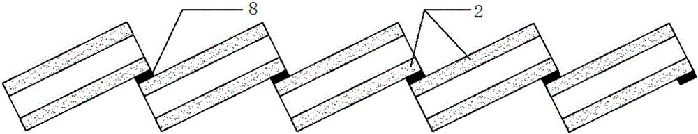
[0052] (2) Apply solder paste to the overlapping parts of the battery sheets, and make lead wires connecting each battery string and junction box. The overlapping width of the front and back of the battery slices is 1.5mm. Every 10 battery slices are stacked in series to form a battery string, and every 6 battery strings are connected in series through welding ribbons.

[0053] (3) Laminate in the order of photovoltaic glass, EVA, battery string, EVA, and photovoltaic glass from bottom to top.

[0054] (4) Use a laminator for lamination at 140°C to cross-link the EVA and combine the battery string with the photovoltaic glass package.

[0055] (5) Perform trimming and EL testing.

[0056] (6) After the package is framed and glued, it is cured for 24 to 48 hours, and...

Embodiment 2

[0059] (1) Classify the efficiency of monocrystalline cells. The cell is of M2 specification. The front electrode is a transparent conductive film-metal composite electrode, and the back electrode is a metal electrode.

[0060] (2) Cut the M2 cell into two halves;

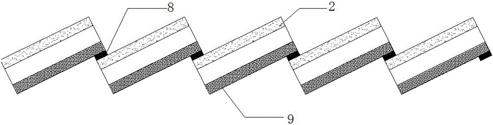
[0061] (3) Use conductive tape to overlap the front and back of adjacent half-cells, and make lead wires connecting each battery string and junction box. The overlapping width of the front and back of the half-cells is 2mm. Every 20 half-cells are stacked in series to form a battery string, and every 6 battery strings are connected in series through welding ribbons.

[0062] (4) Laminate in the order of TPA, EVA, battery string, EVA, and photovoltaic glass from bottom to top.

[0063] (5) Use an autoclave for lamination at 150°C to cross-link the EVA and combine the battery strings, photovoltaic glass and TPA packaging together.

[0064] (6) Perform trimming and EL testing.

[0065] (7) After the package is fram...

Embodiment 3

[0068] (1) The efficiency of the polycrystalline cells is graded. The cell is of M2 specification. The front electrode is a transparent conductive film-metal composite electrode, and the back electrode is a metal electrode.

[0069] (2) Use conductive glue to overlap the front and back of adjacent battery sheets, and make lead wires connecting each battery string and junction box. The overlapping width of the front and back of the battery slices is 1mm. Every 10 battery slices are stacked in series to form a battery string, and every 6 battery strings are connected in series through welding ribbons.

[0070] (3) Laminate in the order of TPA, EVA, battery string, EVA, and photovoltaic glass from bottom to top.

[0071] (4) Use a laminator for lamination at 140°C to cross-link the EVA and combine the battery strings, photovoltaic glass and TPA packaging together.

[0072] (5) Perform trimming and EL testing.

[0073] (6) After the package is framed and glued, it is cured for 2...


PUM

PropertyMeasurementUnit
thicknessaaaaaaaaaa
sizeaaaaaaaaaa

Abstract

The invention discloses a connecting structure of a crystalline silicon photovoltaic cell with transparent electrodes. Front electrodes of cell pieces forming a cell pack string are transparent conductive film-metal composite electrodes, and back electrodes are transparent conductive film-metal composite electrodes or back metal electrodes. The adjacent crystalline silicon photovoltaic cells are connected in series in the mode that the front electrodes and the back electrodes are overlapped, and joints are filled with a conductive binding agent so as to make a cell pack string circuit closed. The transparent conductive film-metal composite electrodes are adopted for the front and / back electrodes of the cells forming a photovoltaic assembly, so that the using amount of metal for making solar cell electrodes is greatly reduced, metal can even be not used at all, the light shielding area is reduced, and the production cost is reduced. The power generating area of the assembly is further increased through overlapped connection of the cells, and thus the power output of the assembly is increased.

Description

technical field [0001] The invention belongs to the technical field of solar cells, in particular to a connection structure of a crystal silicon photovoltaic cell with a transparent electrode. Background technique [0002] Since the first solar cell was born in Bell Laboratories in 1954, crystalline silicon solar cells have been widely used, the conversion efficiency has been continuously improved, and the production cost has continued to decline. At present, crystalline silicon solar cells account for more than 80% of the total global solar cell market, and the conversion efficiency of the production line of components has exceeded 20%. It is expected to be flat in the next few years. As a clean energy source, crystalline silicon solar cells play an increasingly important role in changing the energy structure and alleviating environmental pressure. [0003] Crystalline silicon modules are the core terminal units of photovoltaic power generation, and their conversion effic...

Claims


Application Information

Patent Timeline
Patent Type & Authority Applications(China)
IPC IPC(8): H01L31/0224H01L31/05
CPCH01L31/0224Y02E10/50H01L31/0516H01L31/022466
Inventor 钟宝申李华赵科雄
Owner LONGI SOLAR TECH CO LTD
Why Eureka
Try Eureka