
Low-light-decay ultraviolet LED and manufacturing method thereof

A technology of ultraviolet light and light attenuation, applied in the direction of electrical components, electric solid devices, circuits, etc., can solve the problems of ultraviolet light power reduction, damage to epoxy resin, delamination of inner and outer glue, and large internal stress, etc., to achieve ultraviolet light transmission Improvement of performance and its light attenuation performance, and the effect of eliminating internal stress

Inactive Publication Date: 2016-08-17
浙江单色电子科技有限公司
View PDF9 Cites 2 Cited by
  • Summary
  • Abstract
  • Description
  • Claims
  • Application Information

AI Technical Summary

Problems solved by technology

[0002] In the prior art, when the UVA band (365-415nm) of the purple LED is in-line packaged, the following two methods are adopted: (1) The first method is directly packaged with epoxy resin, and the lamp cup is covered with epoxy resin after packaging. Filling, its disadvantage is that the ultraviolet light will destroy the epoxy resin, resulting in poor ultraviolet light transmission. After a period of use, the ultraviolet light power will drop a lot, which will eventually affect the use
[0003] (2) The second type uses silica gel inside the lamp cup and epoxy resin on the outside. The UV light power is significantly improved. Adhesive delamination and internal stress cause poor consistency of visible light, and the quality and reliability also decline. During wave soldering processing, the dead light rate is high

Method used


Image

  • Low-light-decay ultraviolet LED and manufacturing method thereof
  • Low-light-decay ultraviolet LED and manufacturing method thereof
  • Low-light-decay ultraviolet LED and manufacturing method thereof

Examples


Embodiment

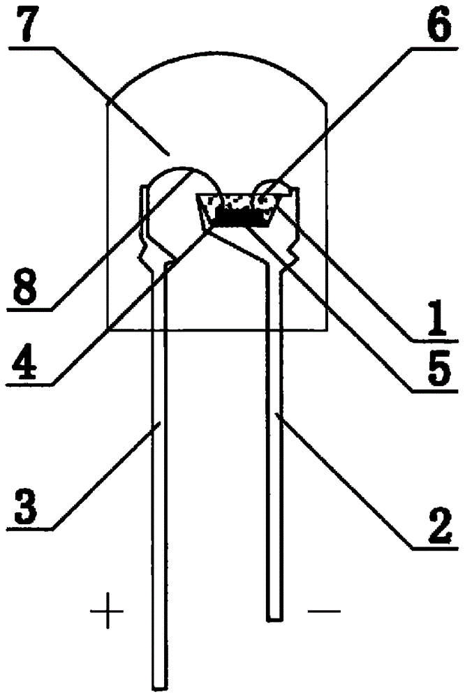
[0026] Example: such as figure 1 As shown, a low light attenuation purple light LED includes a bowl cup 1 with a large upper mouth and a small lower bottom, and a pair of positive and negative electrode guide posts. The positive and negative electrode guide posts further include a positive electrode guide post 3 and a negative electrode guide post 2. The negative pole guide post 2 is directly connected to the bowl cup 1, while the positive pole guide post 3 is spaced apart from the bowl cup 1. A purple light chip 5 is fixed on the inner bottom of the bowl cup 1 through a crystal-bonding glue 4. The UVA band range of the purple light chip 5 is selected at 365 ~415nm. The height of the die-bonding glue 4 is 1 / 3-1 / 2 of the height of the purple chip 5 . The purple light chip 5 is respectively connected to the positive pole guide post 3 and the negative pole guide post 2 through a pair of bonded gold wires 8. After the purple light chip 5 is fixed, the inner glue 6 is filled in th...


PUM


Abstract

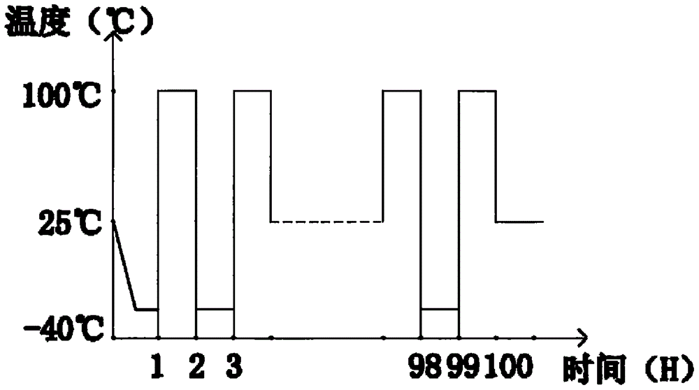
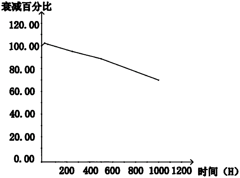
The invention discloses a low-light-decay ultraviolet LED and a manufacturing method thereof. The low-light-decay ultraviolet LED comprises a bowl cup. An ultraviolet chip is fixed to the inner bottom of the bowl cup through crystal fixing glue. The ultraviolet chip is connected with a positive electrode guide post and a negative electrode guide post through a pair of gold bonding wires, the bowl cup is filled with inner glue, and outer glue is packaged outside the bowl cup. The inner glue is organosilicone modified epoxy resin, wherein the glue AB is prepared from, by weight, 10 parts of glue A and 6 parts of glue B. The outer glue is epoxy resin, wherein the glue AB is prepared from, by weight, 100 parts of glue A and 100 parts of glue B. The composition of the outer glue and the composition of the inner glue are roughly consistent, and when the inner glue and the outer glue are combined, the problems of bubbles and layering are completely solved. The expansion coefficient of the inner glue and the expansion coefficient of the outer glue are consistent, internal stress is basically eliminated, the LED can still normally work under 100 times of cold and hot impacts, and due to the fact that components of the inner glue are subjected to silicone modification, the ultraviolet transmission and the light decay performance of the LED are greatly improved.

Description

technical field [0001] The invention relates to the technical field of LED production, in particular to a low light attenuation violet LED and a manufacturing method thereof. Background technique [0002] In the prior art, when the UVA band (365-415nm) of the purple LED is in-line packaged, the following two methods are adopted: (1) The first method is directly packaged with epoxy resin, and the lamp cup is covered with epoxy resin after packaging. The disadvantage of filling is that the ultraviolet light will destroy the epoxy resin, resulting in poor ultraviolet light transmission. After a period of use, the ultraviolet light power will drop a lot, which will eventually affect the use. [0003] (2) The second type uses silica gel inside the lamp cup and epoxy resin on the outside. The UV light power is significantly improved. Glue delamination and internal stress lead to poor consistency of visible light, and the quality and reliability are also reduced. During the wave s...

Claims


Application Information

Patent Timeline
Patent Type & Authority Applications(China)
IPC IPC(8): H01L33/52H01L33/62H01L33/00
CPCH01L33/005H01L33/52H01L33/62H01L2224/48091H01L2224/48247H01L2224/48257H01L2924/181H01L2924/00014H01L2924/00012
Inventor 邱凡
Owner 浙江单色电子科技有限公司
Learn More