Non-array aperture antenna wave beam tilt electronic antenna and implementation method thereof

An antenna beam and antenna technology, applied in the directions of antennas, antenna supports/installation devices, electrical components, etc., can solve the problems of high cost and achieve the effects of low cost, fast scanning speed and high tracking accuracy

Active Publication Date: 2016-08-17
ELECTRIC POWER RES INST OF GUANGDONG POWER GRID
View PDF5 Cites 0 Cited by
  • Summary
  • Abstract
  • Description
  • Claims
  • Application Information

AI Technical Summary

Problems solved by technology

This method can form multiple scanning b

Method used


Image

  • Non-array aperture antenna wave beam tilt electronic antenna and implementation method thereof
  • Non-array aperture antenna wave beam tilt electronic antenna and implementation method thereof

Examples


Embodiment Construction

[0029] The present invention will be further described below in conjunction with examples, but the present invention is not limited to these examples, and under the premise of departing from the gist of the present invention, any improvement made falls within the protection scope of the present invention.

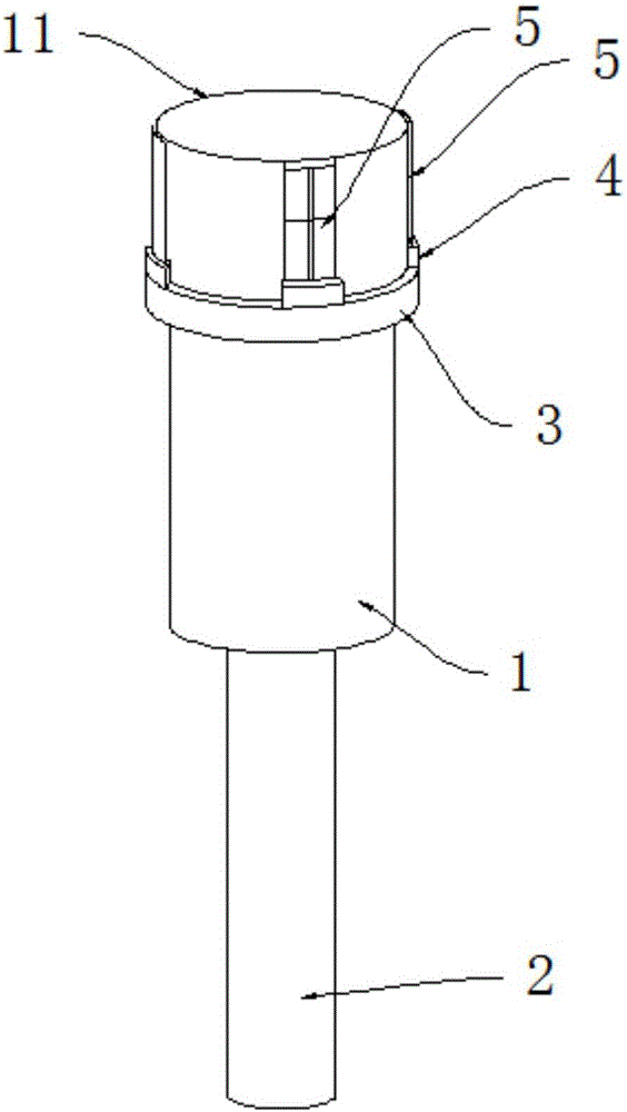
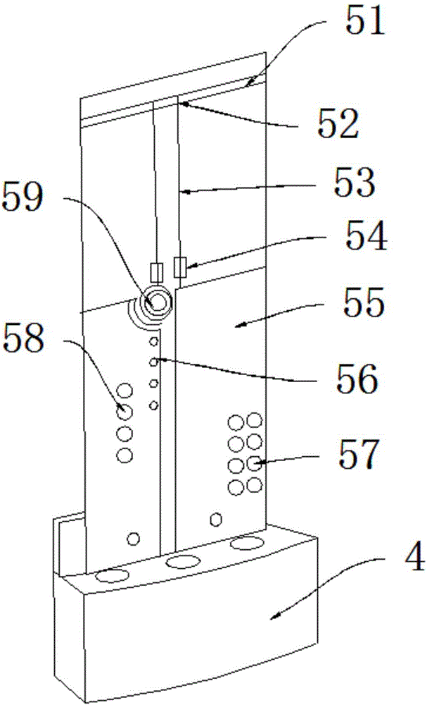
[0030] As shown in the figure, a non-array aperture antenna beam tilting electronic antenna according to the present invention includes an aperture antenna for generating a radiation beam and a control antenna for generating an interference beam, and the aperture antenna is a feedforward reflection surface Antenna, the feed-forward reflector antenna includes a feed horn 1 and a feed waveguide 2, a feed port 11 is provided above the feed horn 1, and a fixing ring 3 is provided on the outer surface of the feed horn 1 , the fixed ring 3 is provided with several fixed seats 4, above the fixed seats are provided with interference antenna 5; the control antenna includes interferen...


PUM


Abstract

The invention discloses a non-array aperture antenna wave beam tilt electronic antenna and an implementation method thereof. The non-array aperture antenna wave beam tilt electronic antenna comprises an aperture antenna and a control antenna. Electric field distribution in a feed source loudspeaker aperture face is changed through an assembly structure and an excitation element antenna used for producing a tilt wave beam, aperture face antenna main wave beam tilt is achieved, and scanning of a wave beam in space is formed through a periodic excitation patch antenna. The aperture antenna is a feedforward reflector antenna. The control antenna comprises an interference antenna, a fixing ring, a fixing base and a compression plate. The polarization mode of the control antennal includes but not limited to linear polarization, dual linear polarization, circular polarization and dual circular polarization. The defects in the prior are overcome, antenna units do not need to be arrayed according to the method, and the non-array aperture antenna wave beam tilt electronic antenna has the advantages of being simple in structure, easy to implement and convenient to control.

Description

technical field [0001] The invention relates to the technical field of beam control, in particular to a non-array aperture antenna beam tilting electronic antenna and a realization method. Background technique [0002] The existing methods for realizing beam scanning mainly include: [0003] 1) Mechanical scanning uses a motor to drive the antenna to periodically move around the connection with the satellite to realize the spatial scanning of the main beam of the antenna. This method is limited by the mechanical structure, the scanning speed is low, and the accuracy is poor. [0004] 2) Monopulse scanning uses the sum-and-difference antenna waveguide network to obtain antenna attitude information and drive the antenna. This method is very accurate, but it is expensive and requires a high-precision tracking receiver. [0005] 3) Phased array scanning uses a large number of transceiver components to form an array, and realizes scanning beams by controlling the phase amplitu...

Claims


Application Information

Patent Timeline
IPC IPC(8): H01Q1/22H01Q1/38H01Q3/26
CPCH01Q1/22H01Q1/38H01Q3/26
Inventor 徐之敬唐文成薛丽丽
Owner ELECTRIC POWER RES INST OF GUANGDONG POWER GRID
Why Eureka
Try Eureka