
A device for liquid casting

A kind of equipment and liquid casting technology, which is applied in the direction of casting equipment, casting molding equipment, equipment for supplying molten metal, etc., which can solve the problem of inability to monitor the liquid in the cavity accurately and in real time, the finished product cannot meet the actual needs, and the supply amount cannot be known, etc. problem, achieve the effect of reducing the risk of air bubbles, simple structure, and avoiding volume shrinkage

Active Publication Date: 2018-06-26
深圳立专信息科技有限公司
View PDF9 Cites 0 Cited by
  • Summary
  • Abstract
  • Description
  • Claims
  • Application Information

AI Technical Summary

Problems solved by technology

[0002] In the metallurgical industry, the most common tool is the mold. The casting process refers to the process of melting the metal into a liquid, introducing it into a liquid casting mold, and then cooling and solidifying it to obtain a product with the same shape as the mold. , because the high-temperature liquid metal will produce bubbles during the injection process, so that the final product contains pores, resulting in a decrease in the quality of the product. In addition, due to the high-temperature liquid metal cooling in the mold, volume shrinkage may occur, but this Since the introduction of the liquid has been stopped, and the specific required supply amount cannot be known, the finished product produced cannot meet the actual needs, and it is impossible to monitor in real time and accurately whether the liquid in the cavity is full.

Method used


Image

  • A device for liquid casting

Examples


Embodiment Construction

[0016] In order to make the object, technical solution and advantages of the present invention more clear, the present invention will be further described in detail below in conjunction with the examples. It should be understood that the specific embodiments described here are only used to explain the present invention, not to limit the present invention.

[0017] The application principle of the present invention will be described in detail below in conjunction with the accompanying drawings.

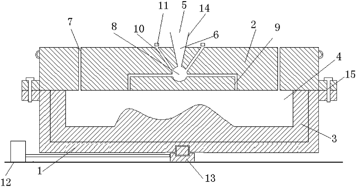
[0018] Such as figure 1 As shown, a device for liquid casting includes a base 1, an upper mold 2, a lower mold 3, a controller (not shown in the figure), a pouring device, and a driving device; the bottom surface of the base is provided with a groove (not shown in the figure), the lower mold 3 is located on the base 1; the mold cavity 4 is formed between the upper mold 2 and the lower mold 3, the top surface of the upper mold 2 is provided with a funnel-shaped casting port 5, and the ...


PUM


Abstract

The invention discloses a device used for liquid casting. The device comprises a base, an upper die, a lower die, a controller, a pouring device and a drive device. A groove is formed in the bottom face of the base, and the lower die is located on the base. A die cavity is formed between the upper die and the lower die. A funnel type casting opening is formed in the top face of the upper die. The upper die is internally provided with a vertical main casting channel connected with the funnel type casting opening. The lower end of the main casting channel is connected with a spherical feeding cavity which is connected with a plurality of branch casting channels, the branch casting channels are communicated with the die cavity, an output channel is further formed in the top end of the spherical feeding cavity, and a distance sensor is arranged on the outlet of the output channel. The drive device comprises a sliding rail, and a slider arranged on the sliding rail. The shape of the slider is matched with that of the groove in the base, and the slider is driven by a cylinder. The controller is electrically connected with the distance sensor and the cylinder. The device used for liquid casting is simple in structure, flowability of liquid in the die cavity is improved, whether overflow happens is monitored in real time, and product quality is improved.

Description

technical field [0001] The invention belongs to the technical field of metal casting, and in particular relates to equipment for liquid casting. Background technique [0002] In the metallurgical industry, the most common tool is the mold. The casting process refers to the process of melting the metal into a liquid, introducing it into a liquid casting mold, and then cooling and solidifying it to obtain a product with the same shape as the mold. , because the high-temperature liquid metal will produce bubbles during the injection process, so that the final product contains pores, resulting in a decrease in the quality of the product. In addition, due to the high-temperature liquid metal cooling in the mold, volume shrinkage may occur, but this Since the introduction of the liquid has been stopped, and the specific required replenishment amount cannot be known, the finished product produced cannot meet the actual needs, and it is impossible to monitor in real time and accurat...

Claims


Application Information

Patent Timeline
Patent Type & Authority Patents(China)
IPC IPC(8): B22D39/00B22D27/08B22C9/08
CPCB22C9/082B22C9/088B22D27/08B22D39/00
Inventor 浦巧生
Owner 深圳立专信息科技有限公司
Learn More