
Rail-craning trolley-frame boring technology

A technology of small frame and rail crane, which is applied in the direction of boring/drilling, manufacturing tools, metal processing equipment, etc. It can solve the problems of low performance, low initial accuracy, high maintenance cost, etc., and achieve high processing accuracy and stability , Reduce production cost, reduce the effect of renovation loss

Inactive Publication Date: 2016-08-24
NANTONG ZHENHUA HEAVY EQUIP MFG
View PDF13 Cites 2 Cited by
  • Summary
  • Abstract
  • Description
  • Claims
  • Application Information

AI Technical Summary

Problems solved by technology

However, due to the large deviation in the accuracy of the hole parts processed by the current production process, and the cumulative errors caused by the assembly and welding of steel components in the later stage, some products have frequent problems such as rail gnawing by large and small cars, and interference between tie rods and guide brackets.
[0003] The JD501 and JD502 simple horizontal boring machines currently in use have been purchased for many years, and their performance is low. They have been used in the open air for a long time, exposed to the sun and rain, shoveled and lifted, etc., which have caused rust and deformation of the guide rails, screw rods, and spindles of the machine tool, resulting in far-reaching accuracy. Lower than the initial accuracy, unable to meet product processing requirements, and the maintenance cost is higher after the accuracy of the machine tool is reduced (the guide rail pair needs to be reworked, the screw and nut replacement, the main shaft, copper sleeve fine grinding, worn gears, bearing replacement)
At present, four boring machines and laser scribing and positioning processing technology are used for the wheel hole of the small frame. The cumulative error caused is larger, which cannot meet the requirements of product processing accuracy

Method used


Image

  • Rail-craning trolley-frame boring technology
  • Rail-craning trolley-frame boring technology
  • Rail-craning trolley-frame boring technology

Examples


Embodiment Construction

[0027] The following examples can enable those skilled in the art to understand the present invention more comprehensively, but the present invention is not limited to the scope of the described examples.

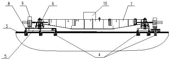
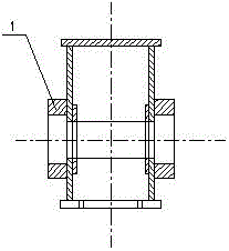
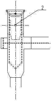
[0028] like Figure 1 to Figure 3 As shown in the figure, a boring process of a rail crane trolley frame, the trolley frame is bored with a CNC gantry fixed beam boring and milling machine, and the specific steps are as follows:

[0029] (1) For the trolley frame with the heavy plate inside the wheel box of the trolley frame, two heavy plates 1 are welded at the corresponding positions on the outside of the wheel box of the trolley frame. A through-hole 2 of Φ40mm is opened on the panel and the bottom plate with an iron-absorbing drill, and the through-hole 2 is set on the track opening line of the trolley frame and the upper and lower positions are consistent;

[0030] (2) Fix the foundation 4 on the cement floor 3, arrange the tire frame 5 on the fixed foundation 4, use ...


PUM


Abstract

The invention relates to a rail-craning trolley-frame boring technology. The rail-craning trolley-frame boring technology includes the steps that for a trolley frame of which heavy plates in a wheel box of the trolley frame are arranged on the inner side, two heavy plates are welded at the corresponding position of the outer side of the wheel box of the trolley frame, and phi 40 mm through holes are formed in a face plate and a bottom plate of the wheel box of the trolley frame with a magnet drill or an air drill, and are formed in crotch opening lines of tracks of the trolley frame and consistent in upper and lower position; foundations are fixed on cement ground, jig frames are arranged on the fixed foundations, the trolley frame is horizontally arranged through jacks, the whole is divided into a wheel-plate-face machining allowance line, a wheel-plate boring machining center line and a datum line; four mattress plates are laid on the jig frames, numerical-control plano determinate-beam boring-milling machines are fixed on the mattress plates, and the trolley frame is bored. The rail craning trolley-frame boring technology has the advantages that the machining quality of components can be effectively improved while production efficiency is improved to a large degree, refurbishing losses are effectively decreased, and production cost is reduced.

Description

technical field [0001] The invention relates to a boring processing technology, in particular to a boring technology for a rail crane small frame. Background technique [0002] The trolley frame is the frame that supports and installs the lifting mechanism and the trolley running mechanism, and is also a metal structure that bears and transmits the lifting load. However, due to the large deviation in the accuracy of the hole parts processed by the current production process, coupled with the cumulative errors caused by the assembly and welding of steel components in the later stage, some products have frequent problems such as rail gnawing by large and small cars, and interference between tie rods and guide brackets. [0003] The JD501 and JD502 simple horizontal boring machines currently in use have been purchased for many years, and their performance is low. They have been used in the open air for a long time, exposed to the sun and rain, shoveled and lifted, etc., which h...

Claims


Application Information

Patent Timeline
IPC IPC(8): B23B35/00B23B41/00
CPCB23B35/00B23B41/00
Inventor 陈剑黄叶锋何华文
Owner NANTONG ZHENHUA HEAVY EQUIP MFG
Learn More