
Thread steel end grinding device

A rebar and equipment technology, applied in the field of rebar end grinding equipment, can solve the problems of high labor intensity, slow manual alignment, low overall efficiency, etc., and achieve high overall efficiency, low labor intensity, and high grinding speed. Effect

Active Publication Date: 2016-08-24
建刚建筑科技南京股份有限公司
View PDF5 Cites 4 Cited by
  • Summary
  • Abstract
  • Description
  • Claims
  • Application Information

AI Technical Summary

Problems solved by technology

[0004] At present, the end of the rebar in the industry is mainly polished manually with simple equipment, including a fixture to clamp the rebar, and then a manually operated grinding mechanism. The manual alignment speed is slow, and there will be steel slag during grinding. Jumping out, high degree of danger, high manual labor intensity, low overall efficiency

Method used


Image

  • Thread steel end grinding device
  • Thread steel end grinding device
  • Thread steel end grinding device

Examples


Embodiment Construction

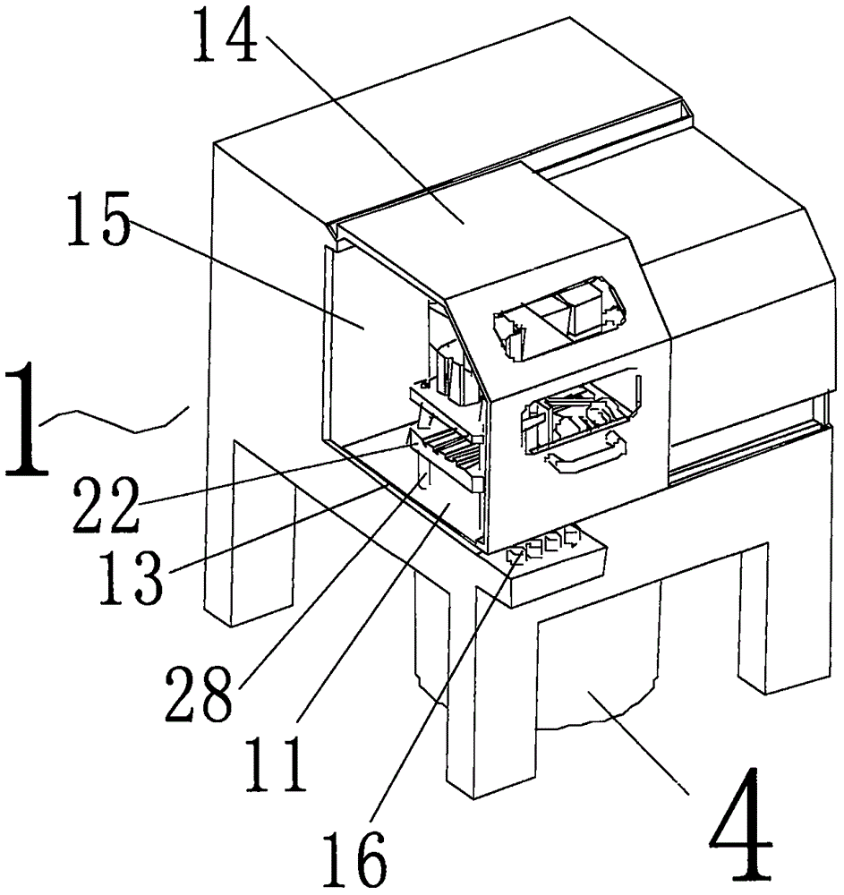
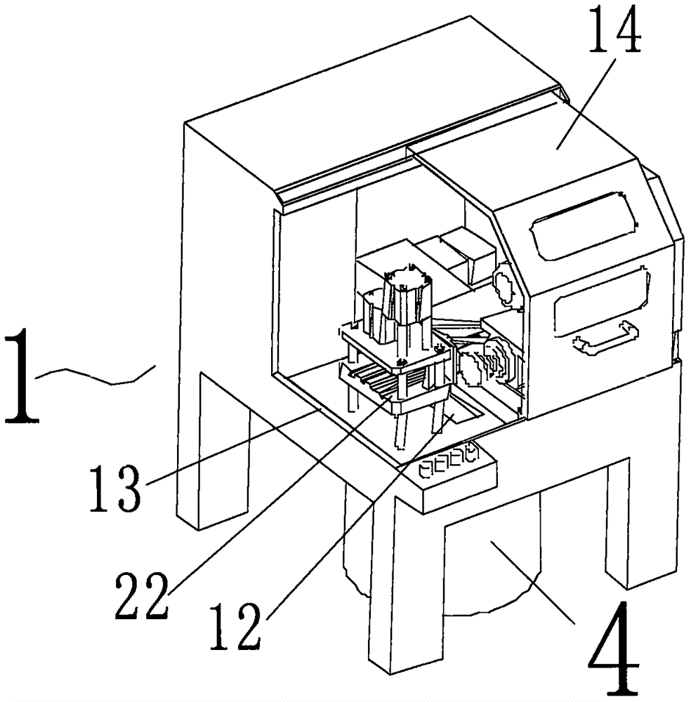
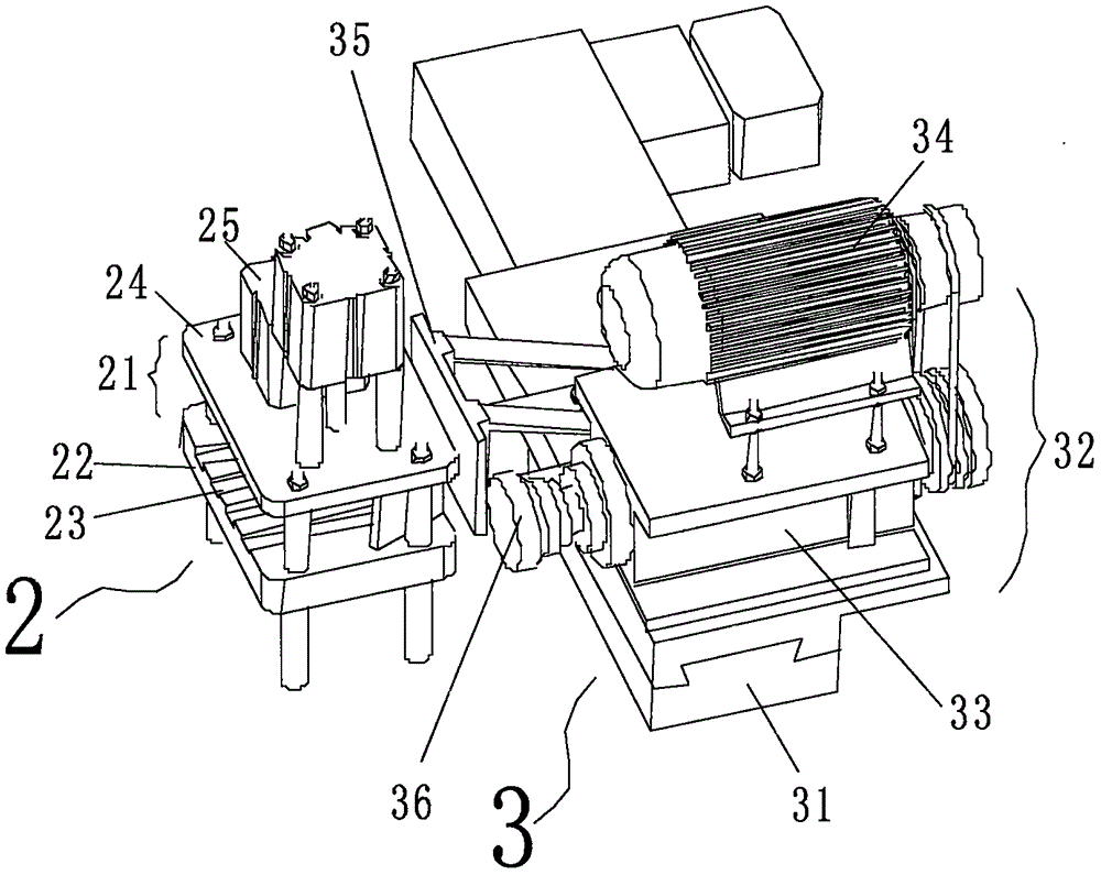
[0024] refer to Figure 1 to Figure 4 , rebar end grinding equipment, including the equipment housing (1), divided into the distribution box room (15) in the equipment housing, the door of the distribution box room (15) is opened on the other side of the equipment housing (1) On the side, the door of the distribution box chamber (15) is closed on the equipment casing (1) through permanent magnet adsorption. The casing (1) is provided with a clamp mechanism (2), a grinding mechanism (3), and the clamp mechanism (2 ) is located on the front side of the grinding mechanism (3);

[0025] The fixture mechanism (2) includes a fixture platform (21), which is divided into upper and lower layers; the lower floor is a support plate (22), and the surface is provided with grooves (23); the upper floor is a pressure plate (24), and the pressure plate (24) The upper surface is a hydraulic oil cylinder (25), the lower surface is provided with a pressure block (26) connected to the top column...


PUM


Abstract

A thread steel end grinding device comprises a device shell and a distribution box chamber divided in the device shell. The thread steel end grinding device is characterized in that a fixture mechanism and a grinding mechanism are arranged in the shell; and the fixture mechanism is arranged on the front side of the grinding mechanism. The thread steel end grinding device is ingenious in structure, capable of being manually operated easily, high in aligning and grinding speed, high in safety, low in manual labor intensity and high in overall efficiency.

Description

technical field [0001] The invention relates to a grinding device, in particular to a grinding device for a threaded steel end, and belongs to the technical field of B24D of IPC classification. Background technique [0002] Rebar is widely used in civil engineering construction such as houses, bridges and roads. Rebar is an indispensable structural material for highways, railways, bridges, culverts, tunnels, flood control, dams and other public facilities, as small as the foundation, beams, columns, walls, and panels of house construction. [0003] The above-mentioned civil works are either exposed to the air or immersed in water. In the later period of service life, they need to withstand the external thermal expansion and contraction and other physical influences. However, due to the original specific heat and expansion of the steel-ribbed concrete structure composed of rebar and cement The coefficients are not the same, so this requires that the gap between the rebar and...

Claims


Application Information

Patent Timeline
IPC IPC(8): B24B7/16B24B41/06B24B41/00B24B41/02B24B27/00
CPCB24B7/162B24B9/04B24B27/0023B24B27/0076B24B41/005B24B41/02B24B41/06B24B55/06
Inventor 金保春
Owner 建刚建筑科技南京股份有限公司
Learn More