
Material dumping and conveying machine

A conveyor and dumping technology, applied to conveyors, rotary conveyors, transportation and packaging, etc., to achieve the effect of reducing labor, reducing production costs, and optimizing production workflow

Inactive Publication Date: 2016-08-24
吕庆民
View PDF0 Cites 0 Cited by
  • Summary
  • Abstract
  • Description
  • Claims
  • Application Information

AI Technical Summary

Problems solved by technology

[0003] In order to increase the conveying capacity, reduce energy, improve the environment, reduce material consumption, and overcome the defects in the technical functions of existing equipment, the present invention provides a dumping machine, which consists of two or more rotating involute impellers Push the material down to the predetermined point by continuous rotation

Method used


Image

  • Material dumping and conveying machine
  • Material dumping and conveying machine

Examples


Embodiment Construction

[0014] The preferred embodiments of the present invention will be described in detail below in conjunction with the accompanying drawings, so that the advantages and features of the present invention can be more easily understood by those skilled in the art, so as to define the protection scope of the present invention more clearly.

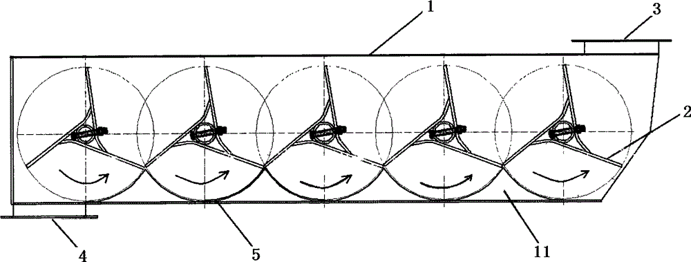
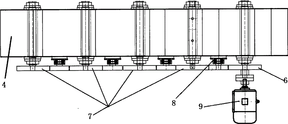
[0015] Such as figure 1 , figure 2 Shown, a kind of dumping conveyor, it comprises the sealed casing 1 that conveys material, and described casing is provided with several involute impellers 2, wherein the two involute impellers that are positioned at the end of the casing are respectively connected with the inlets on the casing. The feed port 3 corresponds to the discharge port 4, and the bottom plate 11 inside the cabinet is provided with a number of arc-shaped grooves 5 corresponding to the above-mentioned involute impeller, and the movement track of the edge of the involute impeller is in line with the arc shape of the bottom plate. The sha...


PUM


Abstract

The invention provides a material dumping and conveying machine. The material dumping and conveying machine comprises a sealed machine box used for conveying materials, wherein a plurality of involute impellers are arranged in the machine box; two involute impellers located on the end parts of the machine box separately correspond to a material inlet and a material outlet in the machine box; a bottom plate in the machine box is provided with a plurality of arc-shaped grooves corresponding to the involute impellers; the moving trajectories of the edges of the involute impellers are consistent with the shapes of the arc-shaped grooves in the bottom plate; the involute impeller located below the material inlet is connected with a motor through a transmission gear; transmission between every two adjacent involute impellers is realized through a gear; and every two adjacent gears are connected through an intermediate gear. By adopting the material dumping and conveying machine, the production working process is optimized; working efficiency is improved; labor is reduced; the installed gross capacity is lowered; loss caused by material leaking and overflowing is reduced; and production cost is lowered.

Description

technical field [0001] The invention relates to a conveying device for inputting or outputting solid powder or granular materials such as fertilizer, chemical industry, biology, and mine, and in particular to a discharge conveyor. Background technique [0002] In my country's chemical fertilizer, chemical, biological, mining and other industries, according to the process requirements, the input or output powdery or granular materials must be transported horizontally or linearly and lifted. Generally, belt or scraper machine is used for flat conveying, and it is common for belt conveying to leak and drop materials during the conveying process. The conveying capacity of scraper conveying is low in equipment with the same volume. The material of the machine is carried out in a sealed chassis, and the conveying is carried out continuously by the rotating impeller. The conveying capacity is large; the straight-line and lifting materials are traditionally conveyed by bucket elevat...

Claims


Application Information

Patent Timeline
IPC IPC(8): B65G29/00
Inventor 吕庆民李旭初王超
Owner 吕庆民
Learn More