Vertical vibration conveying continuous sintering kiln

A vibrating conveying and sintering kiln technology, applied in the field of powder sintering, can solve the problems of environmental heat radiation, discontinuous production, and high use cost, achieve high temperature uniformity and sealing, high product reactivity, and improve reactivity. Effect

Inactive Publication Date: 2016-08-24
48TH RES INST OF CHINA ELECTRONICS TECH GROUP CORP
View PDF6 Cites 2 Cited by
  • Summary
  • Abstract
  • Description
  • Claims
  • Application Information

AI Technical Summary

Problems solved by technology

[0004] (1) Because of its continuous sintering function, it needs some auxiliary equipment, such as propulsion mechanism, atmosphere protection gate, automatic feeding device, automatic unloading device, etc., so the equipment is often bulky, occupies a large area, and consumes a lot of power;
[0005] (2) A large number of devices and components have high requirements for automation design and control, and the failure rate is high;
[0006] (3) High cost and high maintenance cost; high power consumption and high use cost
[0008] (1) Only one batch (tray) of products can be sintered at a time, the production is discontinuous, the output is small, the production efficiency is relatively low, and the consistency of the products is difficult to guarantee;
[0009] (2) Its structure determines that each sintering requires manual feeding, and the labor intensity of workers is high;
[0010] (3) Every time the product is fired and the furnace is turned on, a lot of energy will be wasted and heat radiation will be caused to the environment

Method used


Image

  • Vertical vibration conveying continuous sintering kiln
  • Vertical vibration conveying continuous sintering kiln
  • Vertical vibration conveying continuous sintering kiln

Examples


Embodiment Construction

[0032] The present invention will be described in further detail below in conjunction with the accompanying drawings and specific embodiments.

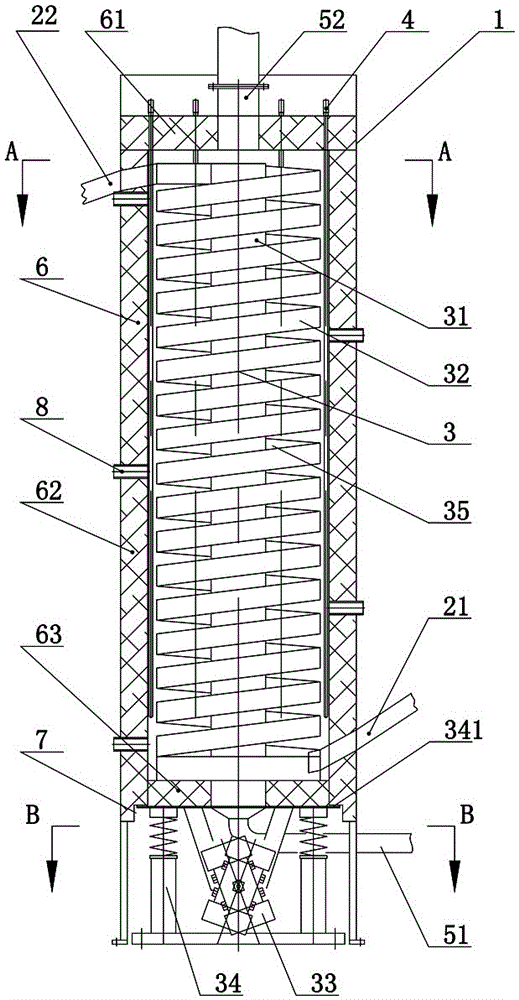
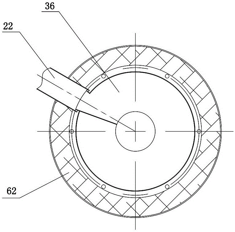
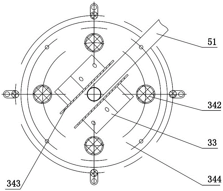
[0033] Such as Figure 1 to Figure 3 As shown, the vertical vibration conveying continuous sintering kiln of this embodiment includes a furnace body 1, a feed pipe 21, a discharge pipe 22, a feeding device 3 and a heating device 4, and the feeding device 3 includes a column 31, a feeding plate 32. The vibrator 33 and the base assembly 34. The base assembly 34 is located at the bottom of the furnace body 1. The column 31 stands vertically in the furnace body 1 and is installed on the base assembly 34. The feeding plate 32 spirals up around the column 31 to form a spiral feeding Passage 35, vibrator 33 is used for driving column 31 and feeding plate 32 vibrations so that powder moves upwards along spiral feeding passage 35, feed pipe 21 communicates with the bottom end of spiral feeding passage 35, discharge pipe 22 and The top of the ...


PUM


Abstract

The invention discloses a vertical vibration conveying continuous sintering kiln. The vertical vibration conveying continuous sintering kiln comprises a kiln body, a feed pipe, a discharge pipe, a conveying device and a heating device. The conveying device comprises a stand column, a conveying plate, a vibrator and a base assembly. The base assembly is located at the bottom of the kiln body. The stand column is perpendicularly erected in the kiln body and mounted on the base assembly. The conveying plate is wound around the stand column upward spirally to form a spiral conveying channel. The vibrator is used for driving the stand column and the conveying plate to vibrate to make powder move upwards along the spiral conveying channel. The feed pipe communicates with the bottom end of the spiral conveying channel. The discharge pipe communicates with the top end of the spiral conveying channel. The heading device is used for heating the powder in the kiln body. According to the vertical vibration conveying continuous sintering kiln, the motion state and the motion manner of the powder are changed, the reactivity of the power during sintering is greatly improved, products are high in reactivity and good in uniformity, the occupied space and energy consumption are reduced, and continuous production is realized. The vertical vibration conveying continuous sintering kiln not only has high-temperature uniformity and sealing performance of small kilns but also has high production efficiency of large kilns.

Description

technical field [0001] The invention relates to the technical field of powder sintering, in particular to a vertical vibration conveying continuous sintering kiln. Background technique [0002] Energy issues have always been a major issue in the development of human society and science and technology. As a green secondary battery with high energy density, lithium-ion batteries have been widely used in consumer electronics such as notebook computers, mobile phones, and cameras. Lithium ion battery cathode active material or negative electrode active material is an important part of lithium ion battery, powder sintering is currently a common method for preparing lithium ion battery cathode active material or negative electrode active material. [0003] There are two main types of powder sintering kilns (mainly referring to the sintering of ferrite, lithium battery cathode materials, vanadium-iron additives, etc.), continuous sintering kiln and discontinuous sintering kiln. C...

Claims


Application Information

Patent Timeline
Patent Type & Authority Applications(China)
IPC IPC(8): F27B1/10F27B1/12F27D3/00
CPCF27B1/10F27B1/12F27D3/00F27D2003/0038
Inventor 曾帅强余永雄刘文
Owner 48TH RES INST OF CHINA ELECTRONICS TECH GROUP CORP
Why Eureka
Try Eureka