Eureka AIR delivers breakthrough ideas for toughest innovation challenges, trusted by R&D personnel around the world.

Fluorescence detection device and detection method thereof

A technology of fluorescence detection and detection method, which is applied in the field of biomedical detection, can solve the problems of fluorescence specific interference, detection error, etc., and achieve the effects of reducing impurities, improving experimental accuracy, and increasing density

Active Publication Date: 2016-08-24
章健 +2
View PDF9 Cites 0 Cited by
  • Summary
  • Abstract
  • Description
  • Claims
  • Application Information

AI Technical Summary

Problems solved by technology

[0005] 1. When it is not cleaned, the transient fluorescence of many impurities interferes with the specificity of fluorescence of fluorescent markers
[0006] 2. The detection magnetic microspheres are distributed in the sample solution at a low concentration, which is easily affected by the interfering substances in the sample solution, resulting in detection errors

Method used


Image

  • Fluorescence detection device and detection method thereof
  • Fluorescence detection device and detection method thereof
  • Fluorescence detection device and detection method thereof

Examples


Embodiment 1

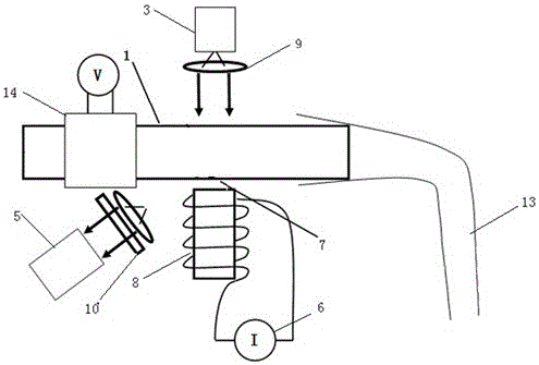
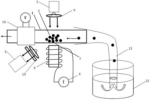
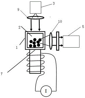
[0054] like figure 1 , figure 2 and image 3 As shown, a fluorescence detection device includes a sample extraction mechanism, a magnetic microsphere collection mechanism and a fluorescence detection mechanism; the sample extraction mechanism includes a liquid suction needle 13, a quartz tube 1 and a liquid suction pump 14, and the liquid suction needle 13 is connected to the quartz tube 1, and the quartz tube 1 is connected to the liquid suction pump 14; the magnetic microsphere collection mechanism is an electromagnet 8 wound by a constant current source 6 power supply coil, and one end of the electromagnet 8 faces the quartz tube 1; The fluorescent detection mechanism includes an excitation light source 3, a first photoelectric converter 5, an excitation light path 9 and a first collecting light path 10, the light of the excitation light source 3 is focused on the quartz tube 1 through the excitation light path 9, and the collection point 7 is the same as the position wh...

Embodiment 2

[0056] This embodiment is on the basis of embodiment 1:

[0057] The quartz tube 1 is a hollow transparent tube with an inner diameter of 0.1 mm.

Embodiment 3

[0059] This embodiment is on the basis of embodiment 1:

[0060] The quartz tube 1 is a hollow transparent tube with an inner diameter of 10 mm.

[0061] The inner and outer diameters of the quartz tube are both square.

[0062] The liquid suction pump 14 is a peristaltic pump.


PUM

PropertyMeasurementUnit
The inside diameter ofaaaaaaaaaa
Particle sizeaaaaaaaaaa

Abstract

The invention provides a fluorescence detection device and a detection method thereof. The device comprises a sample extracting mechanism, a magnetic microsphere gathering mechanism and a fluorescence detection mechanism. The sample extracting mechanism comprises a liquid sucking needle head, a quartz tube and a liquid sucking pump, the liquid sucking needle head is connected with the quartz tube, and the quartz tube is connected with the liquid sucking pump. The magnetic microsphere gathering mechanism is an electromagnet wound with a constant-current-source power supply coil, and one end of the electromagnet faces the quartz tube. The fluorescence detection mechanism comprises an exciting light source, a first photoelectric converter, an exciting light path and a first collecting light path, light of the exciting light source is gathered on the quartz tube through the exciting light path, the gathering point and the position where the electromagnet faces the quartz tube are the same, the first collecting light path is arranged corresponding to the position of the gathering point, and the first photoelectric converter corresponds to the first collecting light path.

Description

technical field [0001] The invention belongs to the technical field of biomedical detection, and in particular relates to a fluorescence detection device and a detection method thereof. Background technique [0002] The application of fluorescence detection technology in medicine and biology has a history of nearly 70 years. It combines with immunological detection technology to form fluorescent immunological technology. With the development and application of immune technology, it has become an It is the most commonly used and most effective detection technique in immunohistochemistry and genomic chemistry. [0003] With the advancement of clinical medicine and science and technology, fluorescence immunoassay technology has developed a variety of practical detection technologies, such as electrochemical fluorescence immunoassay (ECLI), chemiluminescence immunoassay (CLIA), time-resolved fluorescence immunoassay (TRFIA) and other fluorescence immunoassays. technology. Thes...

Claims


Application Information

Patent Timeline
IPC IPC(8): G01N33/577G01N33/533G01N1/28G01N21/76G01N21/64G01N33/78
CPCG01N1/28G01N21/6486G01N21/76G01N33/533G01N33/577G01N33/78
Inventor 吴俊清章健吴冠英
Owner 章健
Why Eureka
Eureka Blog
Learn More