
Splicing type collimating mirror adjustment device and method

A technology for adjusting devices and collimating mirrors, which is applied in installation, optics, instruments, etc., can solve the problems of large distance between collimating mirrors of adjacent units, low system energy utilization rate, and difficulty in ensuring system consistency, so as to improve system consistency performance, improving adjustment efficiency and energy utilization

Active Publication Date: 2018-04-20
BEIJING INST OF ENVIRONMENTAL FEATURES
View PDF6 Cites 2 Cited by
  • Summary
  • Abstract
  • Description
  • Claims
  • Application Information

AI Technical Summary

Problems solved by technology

When the adjustment device adopts this method to adjust the orientation of the collimating mirror of the unit, the rotation center is at the center of the sphere behind, and the X and Y axes will follow the displacement during the adjustment. The consistency of the system is difficult to guarantee, and it needs repeated adjustments to achieve the system Require
In addition, the unit collimator has a large stroke during adjustment, and the distance between adjacent unit collimators must also be large. In this way, more light output by the system cannot be irradiated on the collimator surface, and the energy utilization rate of the system is low.

Method used


Image

  • Splicing type collimating mirror adjustment device and method
  • Splicing type collimating mirror adjustment device and method
  • Splicing type collimating mirror adjustment device and method

Examples


Embodiment Construction

[0039] In order to make the object, technical solution and advantages of the present invention clearer, the present invention will be described in further detail below with reference to the accompanying drawings and preferred embodiments. However, it should be noted that many of the details listed in the specification are only for readers to have a thorough understanding of one or more aspects of the present invention, and these aspects of the present invention can be implemented even without these specific details.

[0040] The inventor of the present invention considers that the existing adjustment device is to set a spherical surface behind the unit collimator mirror, and adjust the orientation of the unit collimator mirror by rotating the spherical surface. When the adjustment device adopts this method to adjust the orientation of the collimating mirror of the unit, the rotation center is at the center of the sphere behind, and the X and Y axes will follow the displacement ...


PUM


Abstract

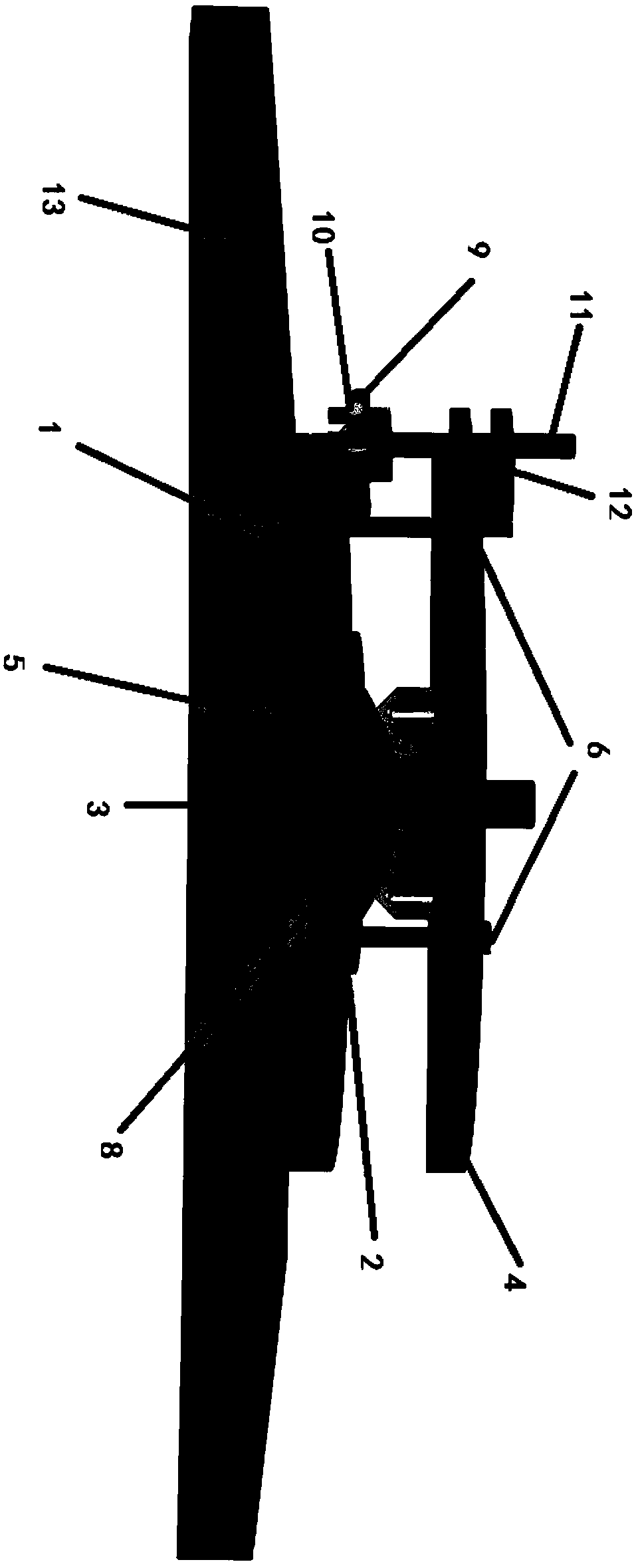
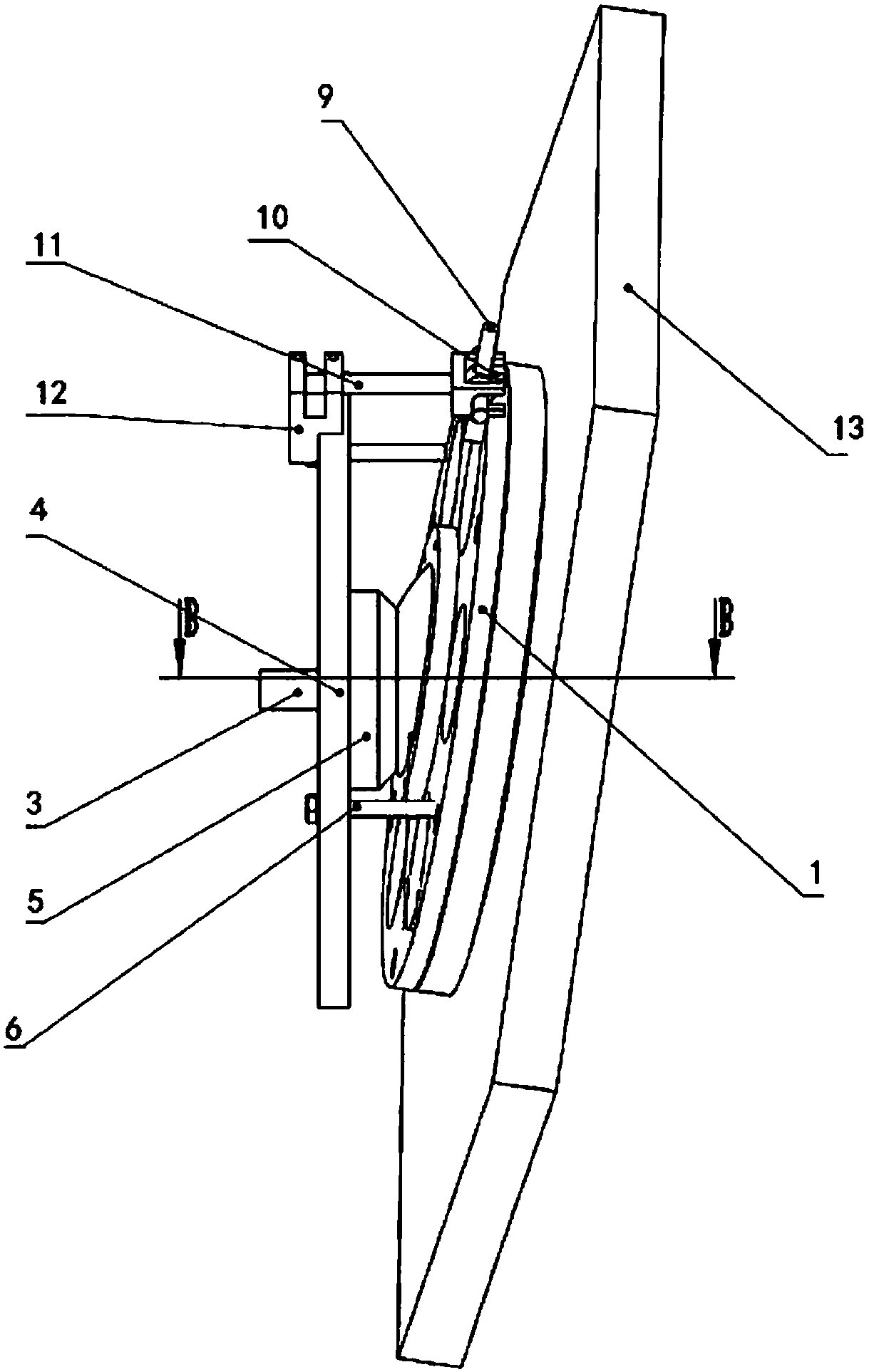
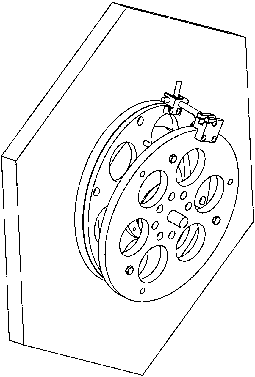
The invention provides a splicing type collimating mirror adjustment device and method, comprising: a connecting flange fixed on the back of the collimating mirror, an adjusting ball seat fixed on the connecting flange, a locking screw installed on the connecting flange, and a lock Lock nuts, fixing seats, rear ball pads and adjusting screws connected by tight screws. Wherein, the surface of the adjusting ball seat is a spherical surface. The rear ball pad is installed on the surface of the fixed seat facing the adjusting ball seat. The surface of the rear ball pad facing the adjusting ball seat is a spherical surface, which is used to limit the movement of the adjusting ball seat. One end of the adjustment screw is connected to the fixed seat, and the other end is against the surface of the connecting flange, which is used to rotate the collimator mirror in azimuth and pitch. The locking screw runs through the middle of the adjusting ball seat, the rear ball pad and the fixing seat. The locking nut is threadedly connected to one end of the locking screw passing through the fixing seat, and is used for locking the relative position of the fixing seat and the connecting flange. The invention can effectively improve the adjustment efficiency and energy utilization rate of the unit collimating mirror.

Description

technical field [0001] The invention relates to the field of optoelectronic technology, in particular to a splicing type collimating mirror adjustment device and method. Background technique [0002] The radiation of the space target flying outside the atmosphere mainly includes solar radiation, the radiation of the earth's reflected sunlight and the earth's radiation. In order to expand the way of space target testing, it is necessary to realistically reproduce the vacuum, low temperature, cold darkness and radiation characteristics of the space environment on the ground, establish a set of technical means and experimental equipment for simulating the extreme conditions of the space environment, and conduct ground simulation verification tests. [0003] The solar simulator is a part of the space environment simulation experiment equipment, which can more accurately simulate the collimation, uniformity and spectral characteristics of solar radiation in the ground vacuum syst...

Claims


Application Information

Patent Timeline
Patent Type & Authority Patents(China)
IPC IPC(8): G02B7/02G02B27/30
CPCG02B7/023G02B27/30
Inventor 彭月王景峰华昊陈红邓蓉苏必达周志远
Owner BEIJING INST OF ENVIRONMENTAL FEATURES
Learn More