Large-view-field imaging device based on prism-fiber coupling

An optical fiber coupling and imaging device technology, applied in optics, optical components, instruments, etc., can solve the problems of high cost, limited field of view, large detector array, etc., to widen the field of view, reduce size, and ensure imaging. quality effect

Inactive Publication Date: 2016-08-24
XIDIAN UNIV
View PDF5 Cites 15 Cited by
  • Summary
  • Abstract
  • Description
  • Claims
  • Application Information

AI Technical Summary

Problems solved by technology

[0007] The purpose of the present invention is to overcome the defects of the above-mentioned prior art, and propose a large field of view imaging device based on prism-fiber coupl

Method used


Image

  • Large-view-field imaging device based on prism-fiber coupling
  • Large-view-field imaging device based on prism-fiber coupling
  • Large-view-field imaging device based on prism-fiber coupling

Examples


Embodiment Construction

[0026] The present invention will be further described below in conjunction with the drawings and embodiments.

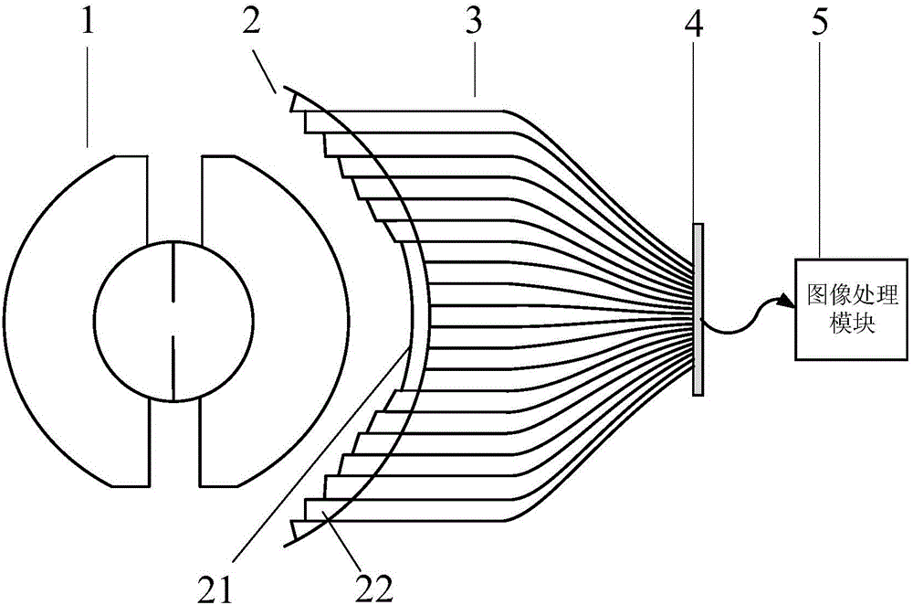
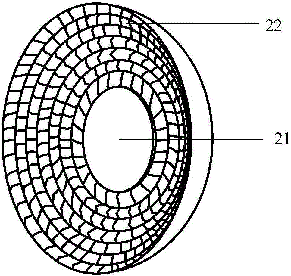
[0027] Reference figure 1 , Is a schematic diagram of the system structure of the present invention, including concentric spherical lens 1, refraction device 2, optical fiber image transmission bundle 3, detector array 4 and image processing module 5; refraction device 2, optical fiber image transmission bundle 3 and detector array 4 They are sequentially arranged on the imaging side of the concentric spherical lens 1, and the central axis of the refraction device 2 and the optical fiber image transmission beam 3 and the center of the detector array 4 are located on the main optical axis of the concentric spherical lens 1. The detector array 4 and image processing Module 5 is electrically connected;

[0028] The concentric ball lens 1 adopts a concentric structure composed of four-layer ball lenses to receive the light energy radiation of the scene; the rotationally symm...


PUM


Abstract

The invention proposes a large-view-field imaging device based on prism-fiber coupling, and is used for solving a technical problem that a conventional fiber coupling imaging device is limited in view field angle and high in cost. The device comprises a concentric ball lens, a refraction apparatus, a coherent fiber bundle, a detector array, and an image processing module. The concentric ball lens is formed by four ball lens layers. The refraction apparatus is located on a Petzval image plane of the concentric ball lens, and employs a spherical surface structure formed by a concentric curved surface lens and a plurality of micro-prisms. The concentric curved surface lens is located at the center of a spherical surface, and the plurality of micro-prisms take the concentric curved surface lens as the center and are densely arranged in the radial direction of the spherical surface to form a multi-layer circular ring. The coherent fiber bundle employs a conical structure. The refraction apparatus, the coherent fiber bundle and the detector array are sequentially arranged at one side of an imaging main axis of the concentric ball lens in a concentric manner, and the detectors are electrically connected with the image processing module. The device can be used for space monitoring, detection alarm, aerial photography, and urban security monitoring.

Description

Technical field [0001] The invention belongs to the field of optical imaging technology, and relates to a large field of view imaging device, in particular to a large field of view imaging device based on prism-fiber coupling, which can be used in the fields of space surveillance, detection warning, aerial aerial photography and urban safety monitoring. Background technique [0002] Field of view and resolution are crucial performance indicators for optical imaging systems, but the relationship between field of view and resolution is mutually restrictive. The short-focus imaging system has a large field of view imaging capability, and the long-focus imaging system can capture high-resolution images, but traditional cameras cannot simultaneously meet the requirements of large field of view and high-resolution imaging. In order to solve this problem, the existing large-field high-resolution imaging systems mainly include small field-of-view scanning imaging systems, fisheye lens im...

Claims


Application Information

Patent Timeline
IPC IPC(8): G02B27/00G02B17/08
CPCG02B27/0075G02B17/08G02B27/0025
Inventor 刘杰涛王娇阳杨莹邵晓鹏许洁张扬
Owner XIDIAN UNIV
Why Eureka
Try Eureka