Multiphase magnetic integration coupling inductor

A coupled inductor and magnetic integration technology, applied in the field of inductors, can solve the problems of complex magnetic coupling structure of the iron core, large coil copper loss, and long coil length, etc., to improve efficiency and dynamic response speed, reduce copper loss, reduce Effect of Small Coil Length

Active Publication Date: 2016-08-24
杨玉岗
View PDF10 Cites 4 Cited by
  • Summary
  • Abstract
  • Description
  • Claims
  • Application Information

AI Technical Summary

Problems solved by technology

The existing multi-phase magnetically integrated coupled inductors have technical deficiencies such as low symmetry of the inductance parameters of each phase, complex magnetic coupling structure of the iron core, long coil length, and large copper loss of the coil.

Method used


Image

  • Multiphase magnetic integration coupling inductor
  • Multiphase magnetic integration coupling inductor
  • Multiphase magnetic integration coupling inductor

Examples


Embodiment 1

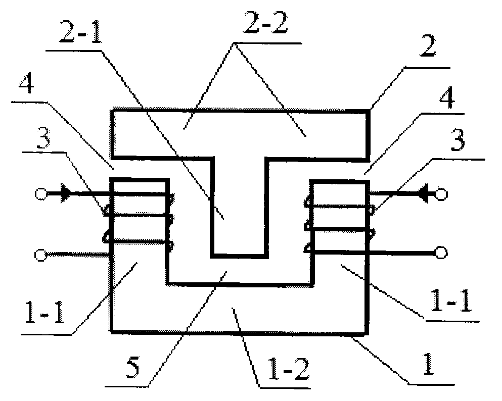
[0020] Refer to attached figure 1 , a two-phase magnetically integrated coupled inductor, composed of a "U"-shaped iron core 1, a "T"-shaped iron core 2 and a coil 3; the magnetic column 2-1 of the "T"-shaped iron core 2 is placed Between the two magnetic columns 1-1 of the "U"-shaped iron core 1; between the yoke 2-2 of the "T"-shaped iron core 2 and the two magnetic poles of the "U"-shaped iron core 1 A certain distance is kept between the pillars 1-1 to form two air gaps 4, between the magnetic yoke 1-2 of the "U" shaped iron core 1 and the magnetic pillar 2-1 of the "T" shaped iron core 2 A certain distance is kept between them to form an air gap 5; the two-phase coils 3 are respectively wound on the two magnetic columns 1-1 of the "U"-shaped iron core 1; the "U"-shaped iron core magnetic columns The cross section of 1-1 and "T" shaped iron core magnetic column 2-1 can be circular, semicircular, oval, triangular, rectangular, square, pentagonal, hexagonal, heptagonal, oct...

Embodiment 2

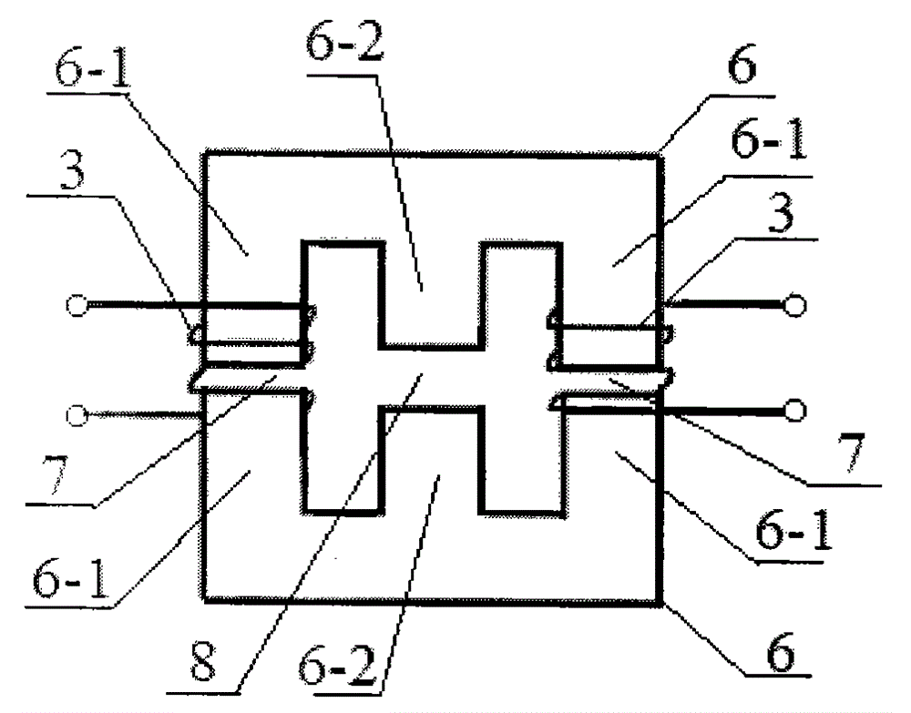
[0022] Refer to attached figure 2 , a two-phase magnetically integrated coupled inductor, an intermediate magnetic column is added between the two magnetic columns 1-1 of the "U"-shaped iron core 1 in Embodiment 1 to form an "E"-shaped iron core 6; Two outer magnetic columns are added at both ends of the yoke 2-2 of the "T"-shaped iron core 2 in Embodiment 1 to form another "E"-shaped iron core 6; in the two "E"-shaped iron cores A certain distance is maintained between the outer magnetic columns 6-1 of 6 to form an air gap 7, and a certain distance is maintained between the middle magnetic columns 6-2 of the two "E" shaped iron cores 6 to form an air gap 8, The two-phase coil 3 is wound on the outer magnetic columns 6 - 1 of the two "E" shaped iron cores 6 .

Embodiment 3

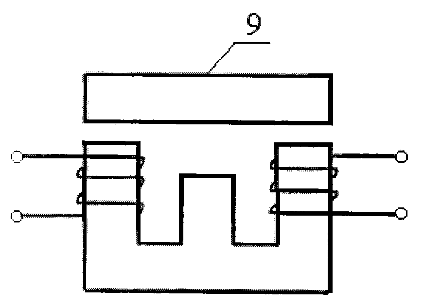
[0024] Refer to attached image 3 , a two-phase magnetically integrated coupled inductor, the three magnetic columns 6-1 and 6-2 of one of the "E"-shaped iron cores 6 in Embodiment 2 are removed to form an "I"-shaped iron core 9.


PUM


Abstract

A multiphase magnetic integration coupling inductor comprises a U-type iron core, a T-type iron core and coils; the magnetic pillars of the T-type iron core are positioned between magnetic pillars of the U-type iron core; an air gap group is formed between the magnetic yoke of the T-type iron core and each magnetic pillar of the U-type iron core; another air gap group is formed between the magnetic yoke of the U-type iron core and each magnetic pillar of the T-type iron core; each magnetic pillar of the U-type iron core are winded by the coil. The advantages are that the multiphase magnetic integration coupling inductor is applied to coupling integration of each phase inductor in an interleaving switch power supply, thus improving symmetry level of each phase inductance parameters, simplifying iron core coupling structure, reducing coil length, saving copper material, reducing coil copper loss, reducing power supply output current and voltage ripples, reducing power supply output filter capacitance, and improving power supply efficiency and dynamic response speed .

Description

technical field [0001] The invention relates to an inductor, in particular to a multi-phase magnetic integrated coupling inductor used for a multi-phase interleaved parallel switching power supply. technical background [0002] In recent years, switching power supplies that provide electrical energy for various electrical equipment are developing in the direction of low voltage, high current, small size, light weight, high efficiency, thinness and integration, including central processing units (Central Processing Units) for computers. Unit, CPU) and Digital Signal Processor (Digital Signal Processing, DSP) and other high-precision, high-speed microprocessors to provide precision power supply voltage adjustment modules, as well as widely used in electric vehicles, hybrid vehicles, uninterruptible power supplies that have emerged in recent years , power quality regulation power supply, aviation power supply, renewable energy power generation and superconducting energy storage...

Claims


Application Information

Patent Timeline
Patent Type & Authority Applications(China)
IPC IPC(8): H01F17/04H01F3/14H01F27/30
Inventor 杨玉岗卢进
Owner 杨玉岗
Why Eureka
Try Eureka