Intelligent three-phase split reactive power compensation device

A technology of three-phase power and phase separation, which is applied in the direction of reactive power adjustment/elimination/compensation, multi-phase network elimination/reduction of asymmetry, etc., which can solve the problems of reduced efficiency, different power factors of three-phase power grids, and poor power quality and other issues to achieve high efficiency and improve the quality of power supply

Inactive Publication Date: 2016-08-24
YANCHENG INST OF TECH +1
View PDF5 Cites 4 Cited by
  • Summary
  • Abstract
  • Description
  • Claims
  • Application Information

AI Technical Summary

Problems solved by technology

In my country's urban and rural civil power grids, the vast majority of electrical equipment adopts a single-phase power supply mode, which requires the distribution transformer to adopt a three-phase four-wire power distribution mode. This makes the power grid in a three-phase unbalanced state under normal operation, resulting in different power factors of the three-phase power grid, resulting in increased power loss, reduced efficiency, and poor power quality.
In order to effectively improve the power factor of the three-phase power supply of the power grid, the existing reactive power compensation device usually adopts a multi-channel three-phase balanced compensation method, but due to the use of multi-level switching compensation, the fineness of the power factor compensation is poor, and Does not substantially solve the problem of different power factors of the three-phase grid
In response to the above-mentioned problem, the scientific research institutes and the technical personnel of the power system are constantly researching and exploring, and using modern science and technology to improve the design of the reactive power compensation device. Although some progress has been made in technology, it is still in practice There are technical challenges that have not yet been overcome

Method used


Image

  • Intelligent three-phase split reactive power compensation device

Examples


Embodiment Construction

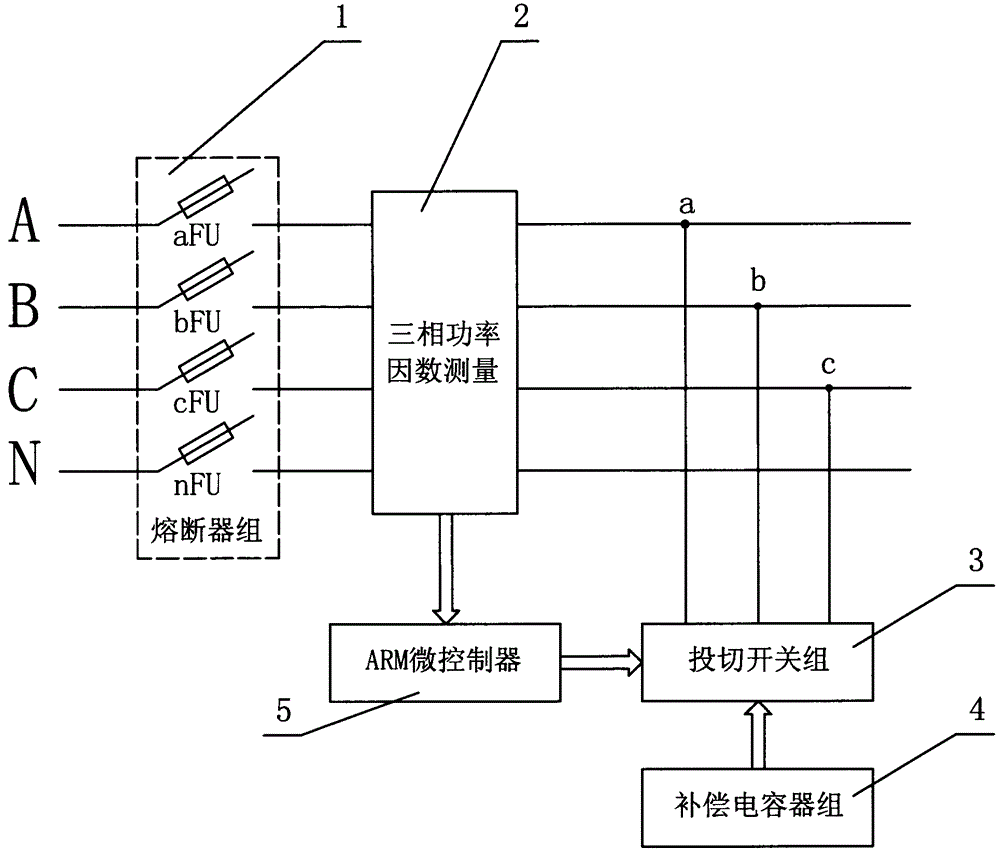
[0012] In the figure, the fuse group 1 includes the fuse aFU on the A-phase line, the fuse bFU on the B-phase line, the fuse cFU on the C-phase line and the fuse nFU on the neutral line N line, three-phase four Lines (A-phase line, B-phase line, C-phase line and neutral line N line) are output through the fuse group 1, and are sequentially electrically connected to the three-phase four-wire access terminal on the three-phase power factor measurement 2. Three-phase power factor measurement 2 includes three sets of current sensors, three sets of voltage sensors and a signal conditioning circuit. Between the phase line and the neutral line N, the signal conditioning circuit is used to analyze and process the three-phase current, three-phase voltage and the corresponding load power factor of each phase. The output voltage and current signals are analog signals, and the output The power factor is a pulse signal with a fixed period; the three-phase power factor measurement 2 is divi...


PUM


Abstract

The invention relates to a power compensation device, in particular, an intelligent three-phase split reactive power compensation device. The intelligent three-phase split reactive power compensation device comprises a fuse group, a three-phase power factor measurement unit, a switching switch group, a compensation capacitor group and an ARM micro controller. The three-phase power factor measurement unit, the compensation capacitor group and the ARM micro controller are combined together, so that the intelligent three-phase split reactive power compensation device can be designed. With the intelligent three-phase split reactive power compensation device adopted, a fast, high-precision, impact-free and three-phase independent reactive power compensation control effect can be effectively realized under the operation of a power grid. The intelligent three-phase split reactive power compensation device can be widely applied to urban and rural civil power grids where three-phase power supply unbalance exists, and can ensure that the power factor of each phase of the three-phase power grids can approximate to or achieve 1, effectively improve the power supply efficiency of the power grids and improve the power supply quality of the power grids.

Description

technical field [0001] The invention relates to a power compensation device, in particular to an intelligent three-phase phase-splitting reactive power compensation device. Background technique [0002] Since the reform and opening up, the national economy has grown rapidly, and "scientific and technological innovation, independent innovation" has become the mainstream of my country's current industrial development. my country's industry is gradually developing in the direction of intensive, energy-saving, emission-reducing, and low-carbon. In my country's urban and rural civil power grids, the vast majority of electrical equipment adopts a single-phase power supply mode, which requires the distribution transformer to adopt a three-phase four-wire power distribution mode. This makes the power grid in a three-phase unbalanced state under normal operation, resulting in different power factors of the three-phase power grid, resulting in increased power loss, reduced efficiency, ...

Claims


Application Information

Patent Timeline
Patent Type & Authority Applications(China)
IPC IPC(8): H02J3/18H02J3/26
Inventor 张美琪赵志祥
Owner YANCHENG INST OF TECH
Why Eureka
Try Eureka