Resonant converter and control method thereof

A technology of resonant converters and transformers, applied in control/regulation systems, converting DC power input to DC power output, instruments, etc., can solve problems such as reducing reliability, increasing voltage gain range, increasing cost and complexity, etc., to achieve Optimized design, wide voltage gain range, low voltage stress effect

Inactive Publication Date: 2016-08-24
NANJING UNIV OF AERONAUTICS & ASTRONAUTICS
View PDF2 Cites 20 Cited by
  • Summary
  • Abstract
  • Description
  • Claims
  • Application Information

AI Technical Summary

Problems solved by technology

[0004] In the case of a wide voltage gain range, scholars often combine LLC converters with three-level or multi-level technology. This type of converter usually uses fixed-frequency control, but requires a lot of power semiconductor devices, which increases the cost and complexity. reduced reliability
Literature "Haibing Hu, Xiang Fang, Frank Chen, Z. John Shen, Issa Batarseh. A Modified High-Efficiency LLC Converter With Two Transformers for Wide Input-Voltage Range Applications[J]. IEEE Transactions on Power Electronics, 2013, 28(4) : 1946-1960." proposed a double transformer structure, the converter can significantly increase the voltage gain range, but also requires a lot of power semiconductor devices

Method used


Image

  • Resonant converter and control method thereof
  • Resonant converter and control method thereof
  • Resonant converter and control method thereof

Examples


Embodiment Construction

[0024] The technical solution of the present invention will be described in detail in conjunction with the accompanying drawings.

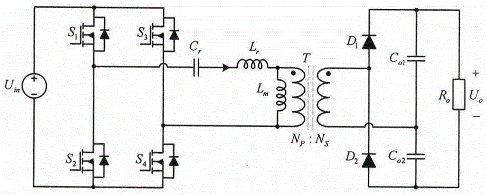
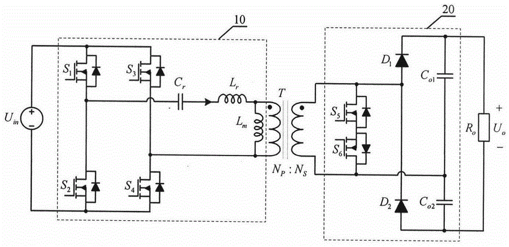
[0025] as attached figure 2 As shown, the resonant converter is composed of an input source (U in ), primary side LLC resonant circuit (10), transformer (T), secondary side active Boost rectifier circuit (20) and output load (R o ), wherein the primary side LLC resonant circuit (10) is composed of the primary side first switching tube (S 1 ), the second primary switching tube (S 2 ), the third switching tube on the primary side (S 3 ), the fourth switching tube on the primary side (S 4 ), resonant capacitor (C r ), resonant inductance (L r ) and magnetizing inductance (L m ), the secondary side active Boost rectifier circuit (20) consists of the secondary side fifth switching tube (S 5 ), the sixth switch tube on the secondary side (S 6 ), the first secondary rectifier diode (D 1 ), the secondary rectifier diode (D 2 ), the first secon...


PUM


Abstract

The present invention discloses a resonant converter and a control method thereof, belonging to the field of the power electronic converter technology. The resonant converter and control method thereof are composed of an input source, an original edge LLC resonance circuit, a transformer, a secondary active Boost rectification circuit and an output load. Based on the traditional LLC resonance converter, the secondary active Boost rectification circuit is substituted for the active Boost rectification circuit so as to realize the fixed frequency phase-shifting control of a converter, the frequency conversion control of the converter and the frequency conversion and fixed frequency phase-shifting combined control to facilitate the design of magnetic elements, reduce the voltage stress of the original edge switch tube and the secondary rectifier tube so as to realize the soft switch of each power semiconductor device, improve the voltage gain range, the efficiency and the power density of the converter and satisfy the requirement of a wide voltage gain margin conversion occasion.

Description

technical field [0001] The invention relates to a resonant converter and a control method thereof, belonging to the technical field of power electronic converters, in particular to the technical field of isolated DC-DC power conversion. Background technique [0002] The isolated DC wide voltage gain range converter is suitable for occasions that require electrical isolation of the input and output and a wide input voltage or output voltage range. This type of converter has a wide range of applications in various fields such as new energy power generation, industry, civil, aerospace, etc. . How to improve the voltage gain range, efficiency and power density of this type of converter has always been a key issue in this technical field. [0003] The LLC resonant converter is a wide voltage gain range isolation converter that has gained widespread attention in recent years, such as figure 1 shown. When the voltage gain is greater than 1, it can realize the soft switching of a...

Claims


Application Information

Patent Timeline
Patent Type & Authority Applications(China)
IPC IPC(8): H02M3/335
CPCY02P80/10
Inventor 吴红飞孙文进葛红娟邢岩
Owner NANJING UNIV OF AERONAUTICS & ASTRONAUTICS
Why Eureka
Try Eureka