
Ultrasonic imaging with acoustic resonant cavity

An ultrasonic and standing wave technology, applied in the field of sensing technology, can solve problems such as limited use

Active Publication Date: 2016-08-24
QUALCOMM INC
View PDF2 Cites 14 Cited by
  • Summary
  • Abstract
  • Description
  • Claims
  • Application Information

AI Technical Summary

Problems solved by technology

In some implementations (e.g., mobile phones, tablet computers, wearable condition monitoring programs, and other mobile devices), the overall thickness of the ultrasonic sensor must be small, on the order of one millimeter thick or less, limiting the capabilities of traditional approaches. use

Method used


Image

  • Ultrasonic imaging with acoustic resonant cavity
  • Ultrasonic imaging with acoustic resonant cavity
  • Ultrasonic imaging with acoustic resonant cavity

Examples


Embodiment Construction

[0041] Several illustrative embodiments will now be described with respect to the accompanying drawings which form a part hereof. While the following describes specific embodiments in which one or more aspects of the invention may be practiced, other embodiments may be used and various modifications may be made without departing from the scope of the invention or the spirit of the appended claims. Revise.

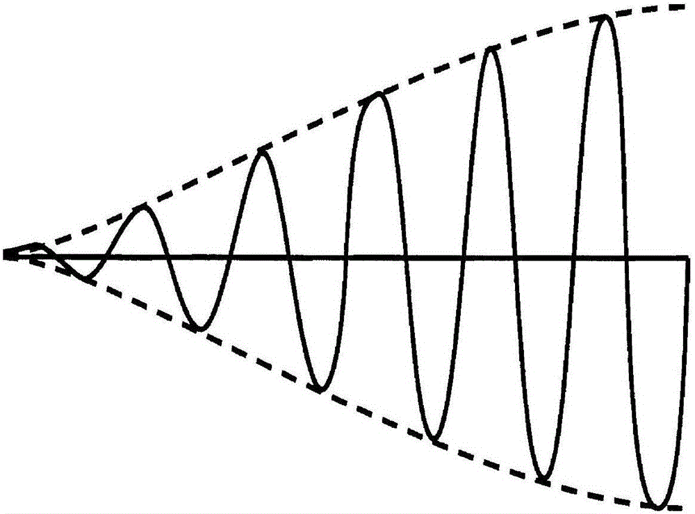
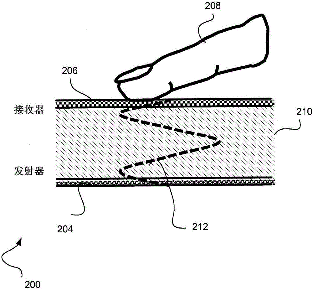
[0042] In general, as an ultrasound signal travels through a medium (eg, a traveling wave), it is observed as a wave with a peak followed by a trough over a period of time. However, when a signal is incident on an acoustically mismatched boundary, the signal may be partially emitted into the adjacent medium and partially reflected back. If an ultrasonic signal travels through a substantially solid medium and the adjacent medium is air, a large portion of the signal can be reflected back into the solid medium, since air tends to create a highly adaptive boundary condition a...


PUM


Abstract

Techniques describe structures and methods for generating larger output signals and improving image quality of ultrasonic sensors by inclusion of an acoustic cavity in the sensor stack. In some embodiments, an ultrasonic sensor unit may be tuned during manufacturing or during a provisioning phase to work with different thicknesses and materials. In some embodiments, a standing wave signal may be generated using an acoustic cavity in the ultrasonic sensor unit for capturing an ultrasonic image of an object placed on a sensor surface. In some implementations, the ultrasonic sensor may include an ultrasonic transmitter, a piezoelectric receiver, a thin film transistor (TFT) layer and a TFT substrate positioned between the transmitter and the receiver, one or more adhesive layers, and optional cover materials and coatings. The thickness, density and speed of sound of the sensor materials and associated adhesive attachment layers may be used to attain the desired acoustic cavity and improved performance.

Description

technical field [0001] The present invention relates generally to sensing technology, and more particularly to ultrasonic sensing technology. Background technique [0002] Sensors detect, and in some cases convert, physical input into electrical or optical output. The device can use the electrical output in a variety of ways. The applications of sensors are widespread and sensors are used in everyday devices such as mobile devices. Specifically, sensors are popular for biometric reading such as reading fingerprints and authenticating users. Traditionally, ultrasound systems have been operated by interpreting echoes from sound waves reflected off distant objects. For example, ultrasonic sensors can generate high-frequency sound waves and evaluate the echoes received back through the sensor. Ultrasonic sensors typically calculate the time interval between sending a signal and receiving an echo to determine the distance to the incident surface of a distant object. In some ...

Claims


Application Information

Patent Timeline
IPC IPC(8): G06K9/00
CPCG06V40/1306G01S7/52017G01S15/02
Inventor 郭乃贵寇斯坦丁·狄米绰夫·乔尔杰夫兰吉特·兰加纳坦菅原奈央
Owner QUALCOMM INC
Learn More