Electromagnetic separator

A magnetic separator and electromagnetic technology, applied in the fields of magnetic separation, solid separation, chemical instruments and methods, etc., can solve the problems of unsatisfactory magnetic separation effect and poor performance of magnetic core, and achieve excellent magnetic separation effect, excellent electromagnetic separation effect, etc. performance, the effect of improving performance

Active Publication Date: 2016-08-31
温州市康尔微晶器皿有限公司
View PDF7 Cites 7 Cited by
  • Summary
  • Abstract
  • Description
  • Claims
  • Application Information

AI Technical Summary

Problems solved by technology

[0004] The object of the present invention is to: aim at the above existing problems, to provide an electromagnetic magnetic separator, which has a simple structure, convenient installation, good sorting effect, excellent electromagnetic performance of the magnetic core, and solves the problem of electromagnetic separation in the prior art in actual use. The magnetic separation effect of the concentrator is not ideal and the performance of the magnetic core is not good

Method used


Image

  • Electromagnetic separator
  • Electromagnetic separator
  • Electromagnetic separator

Examples


Embodiment 1

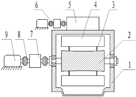
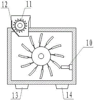
[0036]As shown in the accompanying drawings of the description, an electromagnetic magnetic separator includes a body 1, a driving device 6, a crushing device and a magnetic separation device; the outside of the body 1 is connected to the driving device 6, and the crushing device and magnetic Selection device; the crushing device is set in the feed port 5 on the body 1, the magnetic separation device includes a sorting device and a reverse current device 10; the sorting device is connected to the body 1 through a shaft. In the electromagnetic separator, the driving device 6 is provided with two groups, one group is connected with the crushing device, and the other group is connected with the sorting device. Since the driving speed of the magnetic separation device is different from the driving speed of the crushing device, the magnetic The driving speed of the selected equipment is relatively reduced, so in this scheme, the driving device is set into two groups, and each group ...

Embodiment 2

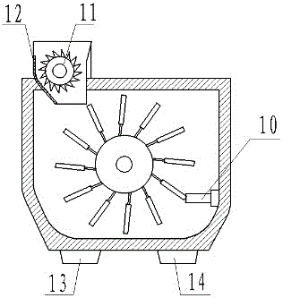
[0048] As shown in the accompanying drawings of the description, an electromagnetic magnetic separator includes a body 1, a driving device 6, a crushing device and a magnetic separation device; the outside of the body 1 is connected to the driving device 6, and the crushing device and magnetic Selection device; the crushing device is set in the feed port 5 on the body 1, the magnetic separation device includes a sorting device and a reverse current device 10; the sorting device is connected to the body 1 through a shaft. In the electromagnetic separator, the driving device 6 is provided with two groups, one group is connected with the crushing device, and the other group is connected with the sorting device. Since the driving speed of the magnetic separation device is different from the driving speed of the crushing device, the magnetic The driving speed of the selected equipment is relatively reduced, so in this scheme, the driving device is set into two groups, and each group...


PUM


Abstract

The invention relates to the field of electromagnetic separators, and discloses an electromagnetic separator. The electromagnetic separator comprises a body, a driving device, a crushing device and a magnetic separating device, wherein the outside of the body is connected with the driving device; the crushing device and the magnetic separating device are arranged in the body; the crushing device is arranged in a feeding opening in the body; the magnetic separating device comprises sorting equipment and reverse current equipment; and the sorting equipment is connected to the body through a shaft. The electromagnetic separator is simple in structure, speedy and convenient to mount and good in sorting effect, the electromagnetic property of a magnetic core is excellent, and the problems that an electromagnetic separator in the prior art is not ideal in magnetic separation effect and the using performance of a magnetic core is poor in actual use are solved.

Description

technical field [0001] The invention relates to the field of mechanical magnetic separators on mines, in particular to an electromagnetic magnetic separator. Background technique [0002] Magnetic separators are used to remove iron powder from reusing powdery granules. Magnetic separators are widely used in resource recovery, wood industry, mining industry, kiln industry, chemical, food and other factories. They are suitable for magnetite, magnetic Wet magnetic separation of pyrite, roasted ore, ilmenite and other materials is also used for iron removal operations of coal, non-metallic minerals, building materials and other materials. It is one of the most widely used and highly versatile machines in the industry . The magnetic separation process is achieved in the magnetic field of the magnetic separator, with the help of magnetic force and mechanical force on the ore particles to achieve separation. Different magnetic ore particles move along different trajectories, so th...

Claims


Application Information

Patent Timeline
Patent Type & Authority Applications(China)
IPC IPC(8): B03C1/02B23P15/00
CPCB03C1/02B23P15/00
Inventor 张荣斌
Owner 温州市康尔微晶器皿有限公司
Why Eureka
Try Eureka