Retaining ring short-flow manufacturing process

A manufacturing process and short-flow technology, applied to metal processing equipment, etc., can solve the problems of high processing cost, low pass rate, and many forging processes, and achieve the effect of increasing product pass rate, reducing processing cost, and reducing forging processes

Active Publication Date: 2016-08-31
海南岛隆环保科技有限公司
View PDF7 Cites 3 Cited by
  • Summary
  • Abstract
  • Description
  • Claims
  • Application Information

AI Technical Summary

Problems solved by technology

[0003] The material utilization rate is low, generally around 30%
[0004] There are many forging processes and a long period, usually through six forging processes, and the processing cost is high
[0005] The qualified rate is low. Since the retaining ring steel has high deformation resistance and strong crack sensitivity, cracks are easy to occur on the surface of each forging process. It is necessary to remove the surface cracks before entering a forging process. If the cracks are not cleaned, the product is easily scrapped.

Method used


Image

  • Retaining ring short-flow manufacturing process
  • Retaining ring short-flow manufacturing process

Examples


Embodiment Construction

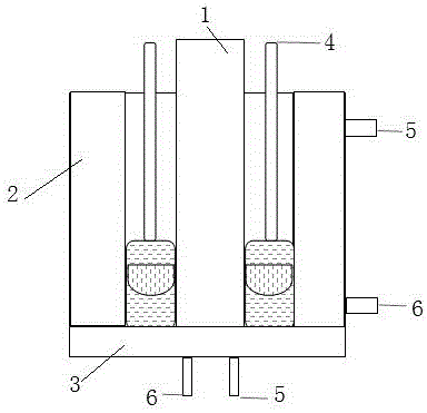
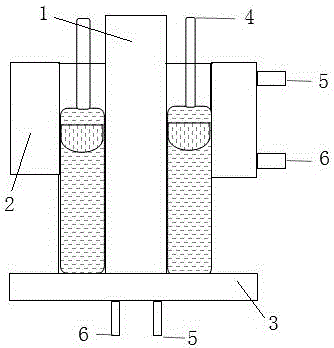
[0023] Attached below figure 1 , 2 The present invention is described in detail:

[0024] A short process manufacturing process for a retaining ring is characterized in that the method comprises the steps of:

[0025] A) Electroslag hollow steel pipe: The production principle of electroslag continuous casting moving mandrel is adopted, that is, the self-consumable electrode 4 is continuously and evenly melted, and the slag surface continues to rise. After reaching the predetermined height, start the dummy device, and pull the hollow steel ingot downward at a slow speed Moving, the casting speed is proportional to the melting speed of the consumable electrode 4. The two reach a balanced state. After the smelting is completed, the steel ingot and the water-cooled mandrel 1 are lifted out, and the water-cooled mandrel 1 is taken out. The hollow steel pipe retaining ring is completed. ;

[0026] Dummy device: water-cooled dummy plate 3

[0027] The outer diameter of the hollow...


PUM

PropertyMeasurementUnit
yield strengthaaaaaaaaaa

Abstract

The invention relates to a retaining ring short-flow manufacture technology, and belongs to the electroslag technology field. <{EN2}>The method comprises the steps of A) electroslag hollow steel pipe, namely employing electroslag continuous casting mobile core rod production principle, i.e. consumable electrode for continuously uniform fusing, so that a slag surface rises continuously to start an ingot device after reaching a predetermined height, so as to tract the hollow steel ingot move downwards slowly; the tract speed is in direct proportion with the consumable electrode fusing speed, and the two speeds are balanced; after melting, the steel ingot and the core rod are lifted; the core rod is taken out and the hollow steel pipe retaining ring is completed; B) pulling; C) solid melting; D) mechanical processing, namely processing the internal and external surface of a blank and two transverse planes until ho black dots appear; E) cold expansion, namely deforming the retaining ring by means of hydraulic pressure by using a water press over 8000ton through a special die to obtain a retaining ring that has a high strength that is larger than or equal to 1000 Mpa; F) tempering, namely employing insulating the retaining ring between 35- DEG C and 400 DEG C for a long time after cold expansion to eliminate the deformation pressure.

Description

technical field [0001] The invention relates to a short-flow manufacturing process for a retaining ring, which belongs to the technical field of electroslag technology. Background technique [0002] The traditional manufacturing process of the retaining ring is to use electroslag remelted solid steel ingots as raw materials, after heating and upsetting, punch holes with large-scale forging equipment, and forge the blank of the retaining ring through multiple processes of repeated forging, elongation, and hole expansion. Its disadvantages are as follows: [0003] The material utilization rate is low, generally around 30%. [0004] There are many forging processes and the cycle is long, usually through six forging processes, and the processing cost is high. [0005] The pass rate is low. Since the retaining ring steel has high deformation resistance and strong crack sensitivity, cracks are prone to occur on the surface of each forging process. It is necessary to remove the s...

Claims


Application Information

Patent Timeline
Patent Type & Authority Applications(China)
IPC IPC(8): B21J5/00
CPCB21J5/002
Inventor 饶云福
Owner 海南岛隆环保科技有限公司
Why Eureka
Try Eureka