Clamping device for electrical mechanical equipment production

A technology of electrical machinery and clamping devices, which is applied in the direction of positioning devices, metal processing equipment, metal processing machinery parts, etc., can solve the problems of reducing the effect of use, affecting the effect of clamping, and reducing the efficiency of work, so as to improve the use of Effect, effect of increasing clamping, effect of shortening working time

Active Publication Date: 2016-08-31
WUXI KING MO MACHINERY
View PDF5 Cites 20 Cited by
  • Summary
  • Abstract
  • Description
  • Claims
  • Application Information

AI Technical Summary

Problems solved by technology

[0003] Electrical mechanical equipment is a general term for generators, transformers, power lines, circuit breakers and other equipment in the power system. At present, when processing and manufacturing electrical mechanical equipment, it is necessary to clamp and fix electrical mechanical equipment for better It is convenient for the staff to process and manufacture, but the existing tightening equipment generally has a single structure and complicated operation, which is inconvenient for the staff to use better, reduces the effect of use, and increases the working time. Moreover, the existing tightening equipment The clamping effect is not good, and it is prone to loosening, which will affect the normal clamping effect and reduce the work efficiency

Method used


Image

  • Clamping device for electrical mechanical equipment production
  • Clamping device for electrical mechanical equipment production
  • Clamping device for electrical mechanical equipment production

Examples


Embodiment Construction

[0015] The following will clearly and completely describe the technical solutions in the embodiments of the present invention with reference to the accompanying drawings in the embodiments of the present invention. Obviously, the described embodiments are only some, not all, embodiments of the present invention. Based on the embodiments of the present invention, all other embodiments obtained by persons of ordinary skill in the art without making creative efforts belong to the protection scope of the present invention.

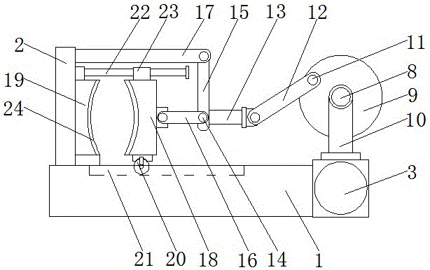
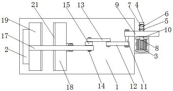
[0016] see Figure 1-3 , the present invention provides a technical solution: a clamping device for the production of electrical mechanical equipment, including a bottom plate 1, one side of the top of the bottom plate 1 is fixedly connected with a vertical plate 2, the vertical plate 2 is close to the side of the first clamping plate 18 and The top of the second clamping plate 19 is fixedly connected with a slide bar 22, and the end of the slide bar 22 away f...


PUM


Abstract

The invention discloses a clamping device for electrical mechanical equipment production. The clamping device comprises a bottom plate. One side of the top of the bottom plate is fixedly connected with a vertical plate. One side of the bottom plate is fixedly connected with a motor. A rotating shaft of the motor is fixedly connected with a connecting rod through a coupler. The surface of the end, far away from the motor, of the connecting rod is fixedly connected with a belt wheel. The belt wheel is in transmission connection with a rotation wheel through a belt. A rotation rod is fixedly connected to the rotation wheel. The surface of the rotation rod is fixedly connected with a disk. A supporting device is arranged at the end, far away from the rotation wheel, of the rotation rod. The clamping device for electrical mechanical equipment production solves the problems that existing clamping equipment is commonly single in structure and complex in operation, and the clamping device can be used by a user more conveniently. The using effect is greatly improved, the work time is shortened, the clamping effect of the clamping equipment is improved, the phenomenon that loosening is likely to happen is avoided, the normal clamping effect is guaranteed, and the work efficiency is improved.

Description

technical field [0001] The invention relates to the technical field of electrical machinery production equipment, in particular to a clamping device for production of electrical machinery equipment. Background technique [0002] Electricity is a general term for disciplines or engineering fields such as the production, transmission, distribution, use, and electrical equipment manufacturing of electrical energy. It is a science that uses electrical energy, electrical equipment, and electrical technology to create, maintain, and improve limited spaces and environments. Three aspects of electric energy conversion, utilization and research, including basic theory, application technology, facilities and equipment, etc. [0003] Electrical mechanical equipment is a general term for generators, transformers, power lines, circuit breakers and other equipment in the power system. At present, when processing and manufacturing electrical mechanical equipment, it is necessary to clamp a...

Claims


Application Information

Patent Timeline
Patent Type & Authority Applications(China)
IPC IPC(8): B23Q3/06B25B5/12B25B5/16B25B5/02
CPCB23Q3/066B25B5/02B25B5/127B25B5/16
Inventor 王守益
Owner WUXI KING MO MACHINERY
Why Eureka
Try Eureka