
Cooling module

A technology of cooling modules and cooling liquids, applied to the arrangement of cooling combination of power plants, fixed conduit components, lighting and heating equipment, etc., can solve the problem of ensuring the stable performance of the second radiator 21 and affecting the performance of the second radiator 21 etc. to achieve the effect of size reduction, size reduction, and enhanced condensation performance

Active Publication Date: 2016-08-31
HANON SYST
View PDF5 Cites 7 Cited by
  • Summary
  • Abstract
  • Description
  • Claims
  • Application Information

AI Technical Summary

Problems solved by technology

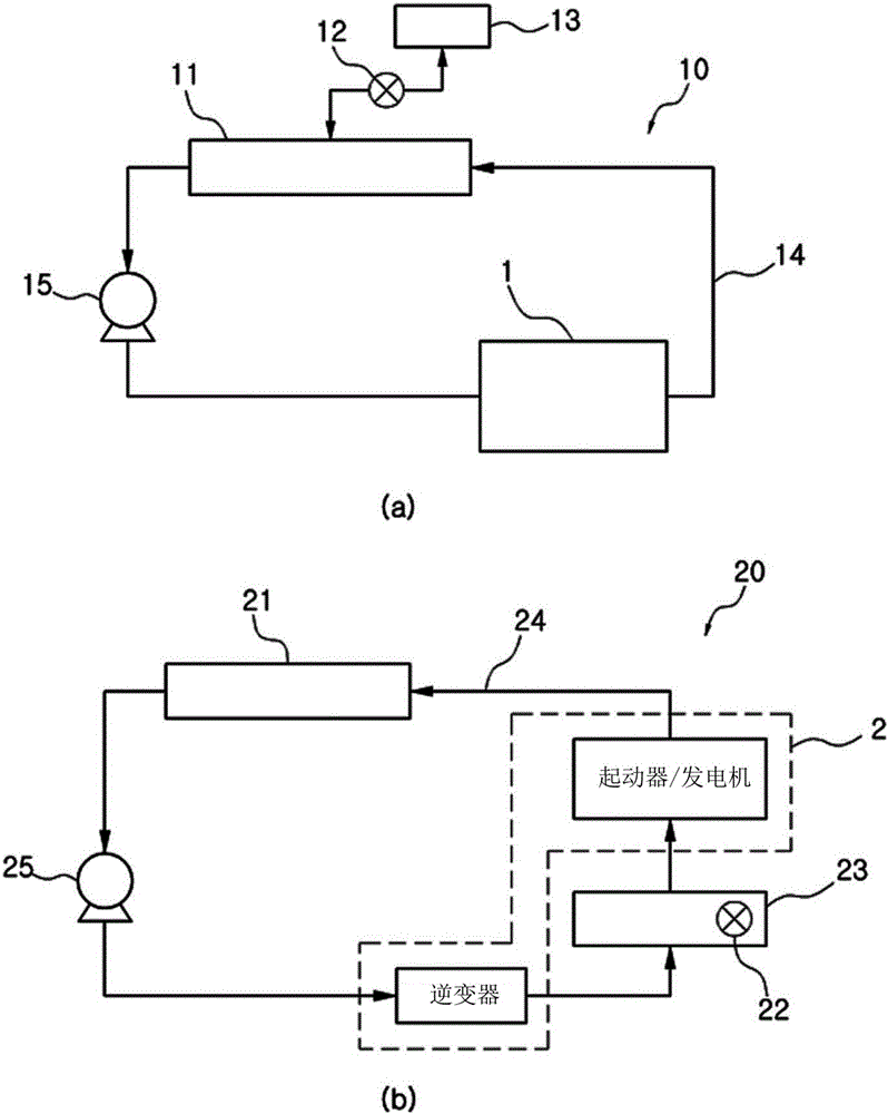
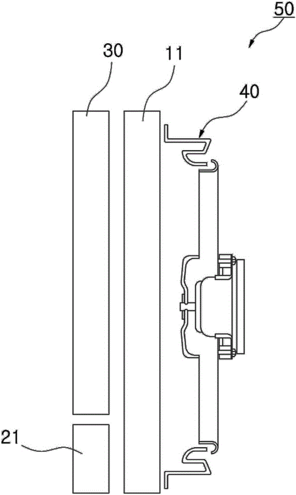
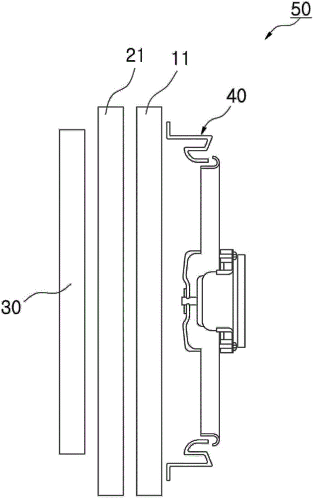
However, in image 3 In the configuration, the air heated by the condenser 30 passes through the second radiator 21, which negatively affects the performance of the second radiator 21
[0016] In addition, the temperature of the air supplied to the second radiator 21 is significantly different according to the load amount of the condenser 30, making it difficult to ensure stable performance of the second radiator 21

Method used


Image

  • Cooling module
  • Cooling module
  • Cooling module

Examples


Embodiment Construction

[0047] Hereinafter, a cooling module 1000 according to an embodiment of the present invention will be described in detail with reference to the accompanying drawings.

[0048] Figure 4 to Figure 6B is a perspective view, an exploded perspective view and a front view of a cooling module 1000 according to an embodiment of the present invention, Figure 7 is a schematic cross-sectional view of a region forming the second heat sink 200 of the cooling module 1000 according to an embodiment of the present invention, Figure 8 is a schematic cross-sectional view of a region forming the first condenser 300 of the cooling module 1000 according to an embodiment of the present invention.

[0049] The cooling module 1000 according to an embodiment of the present invention includes a first radiator 100 , a second radiator 200 , a first condenser 300 and a second condenser 400 .

[0050] The first radiator 100 (for cooling the components of the fuel cell stack) may include: a pair of wat...


PUM


Abstract

A cooling module provided by the invention includes a first radiator configured to cool a fuel cell stack. A second radiator is positioned in a predetermined area in front of the first radiator in an air flow direction and configured to cool an electronic component. A first condenser is positioned in the other remaining area in front of the first radiator in the air flow direction and heat-exchanged with ambient air to condense a refrigerant. A second condenser is provided within the second radiator and heat-exchanged with a coolant to condense a refrigerant. The second radiator and the first condenser are positioned alongside each other in front of the first radiator. The second condenser is provided within the second radiator. The condensate performance of the coolant is improved, and the size of the cooling module is reduced.

Description

technical field [0001] The present invention relates to a cooling module, and more particularly to such a cooling module, wherein a second radiator and a first condenser are arranged side by side in front of the first radiator, and the second condenser is arranged on the second radiator inside the device, thereby reducing size while supporting high refrigerant condensation performance. Background technique [0002] Generally, in a vehicle equipped with an internal combustion engine, heat generated at the time of engine operation is transferred to the cylinder head, pistons, and valves, and therefore, when the temperature of these components rises excessively, they thermally expand or degrade, thereby Cause strength degradation, shorten the life of the engine, deteriorate the combustion, cause knocking or pre-ignition, and reduce the output of the engine. [0003] In addition, when the fuel cell stack is not completely cooled, the oil film of the inner peripheral surface of ...

Claims


Application Information

Patent Timeline
Patent Type & Authority Applications(China)
IPC IPC(8): B60K11/04
CPCB60K11/04F28D1/0452F28D2021/0031F28D2021/0043F28D2021/0084F28D2021/0091F28F9/02F28F9/0234F28F9/262
Inventor 张峻一李钟杜
Owner HANON SYST
Learn More