Method, system and use for decomposing co2

A CO2, gas mixture technology, applied in chemical instruments and methods, lighting and heating equipment, liquefaction and other directions, can solve the problems of the need to strengthen emission reduction technology, cost, efficiency and energy consumption problems, to achieve sufficient decomposition of CO2, cost Low, high decomposition efficiency

Active Publication Date: 2019-02-05
TSINGHUA UNIV
View PDF1 Cites 2 Cited by
  • Summary
  • Abstract
  • Description
  • Claims
  • Application Information

AI Technical Summary

Problems solved by technology

[0003] From the background above, it can be seen that carbon capture and utilization is the 2 An important way to reduce emissions, the current large-scale emission reduction technology is mainly through CO 2 Compressed to 10 to 15MPa and then piped to deep sea for storage, but this technology has problems in terms of cost, efficiency and energy consumption
[0004] Therefore, the current CO 2 Emission reduction technology still needs to be strengthened

Method used


Image

  • Method, system and use for decomposing co2
  • Method, system and use for decomposing co2
  • Method, system and use for decomposing co2

Examples


Embodiment approach

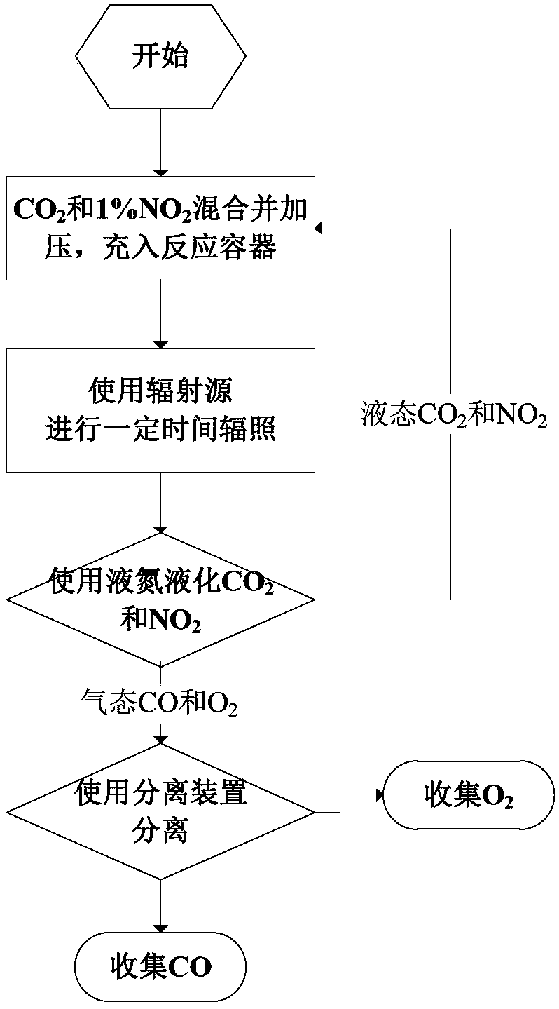
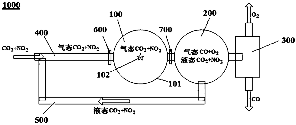
[0070] According to some specific examples of the present invention, refer to figure 1 with image 3 , the present invention decomposes CO 2 The structure of the system and its implementation method are as follows:

[0071] (1) Place CO around the radioactive device or material (i.e. radiation source 102) 2 The reaction pipes or containers that pass through can be made of quartz refractory materials; radioactive materials (such as isotope sources) can also be directly placed inside the reaction container. At this time, the reaction container can directly use shielding ionizing radiation such as lead tanks. container;

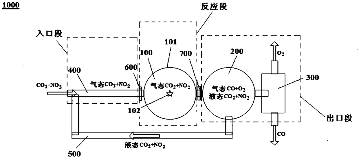
[0072] (2) Divide the reaction pipeline or container into three parts, including: the inlet section (including CO 2 delivery device 400), reaction section (including radiation device 100), outlet section (including liquefaction treatment device 200 and separation device 300), the volume ratio is 1:1:1), the inlet section and outlet section of the reaction pi...

Embodiment 1

[0087] refer to Figure 1-Figure 3 , using the decomposition CO of the present invention 2 The system decomposes CO 2 ,details as follows:

[0088] (1) Place CO around the radioactive device or material (i.e. radiation source 102) 2 The reaction pipes or containers that pass through can be made of quartz refractory materials; radioactive materials (such as isotope sources) can also be directly placed inside the reaction container. At this time, the reaction container can directly use shielding ionizing radiation such as lead tanks. container;

[0089] (2) Divide the reaction pipeline or container into three parts, including: the inlet section (including CO 2 delivery device 400), reaction section (including radiation device 100), outlet section (including liquefaction treatment device 200 and separation device 300), the volume ratio is 1:1:1), the inlet section and outlet section of the reaction pipeline are respectively provided with Shut off the valve so that the outlet s...


PUM


Abstract

The invention discloses a CO2 decomposing method, a CO2 decomposing system and application thereof. The CO2 decomposing method includes: putting CO2 in a radiation range of a radiation source so as to utilize ionizing radiation to decompose CO2 into CO and O2. By the CO2 decomposing method, CO2 decomposition can be realized effectively to obtain CO and O2 having industrial application value; besides, devices or materials releasing ionizing radiation are fully utilized, waste recycling is realized and equivalent to zero energy consumption, cost is low, and efficiency is high.

Description

technical field [0001] The present invention relates to CO 2 Break down technology areas. Background technique [0002] Since the industrial revolution, CO produced by social and economic activities that consume a lot of fossil energy in the world, especially in developed countries 2 Cumulative emissions have led to a significant increase in the concentration of greenhouse gases in the atmosphere, and the resulting consequences of global warming, sea level rise, and extreme climate events have brought huge challenges to human survival and development in the future. As early as the end of the 19th century, the Swedish scientist Swan Ahrrenius proposed CO 2 Warnings that the emissions could lead to global warming did not gain widespread public attention until the 1970s. The "United Nations Framework Convention on Climate Change", which came into force in 1994 and was negotiated by more than 150 countries of the United Nations, and the "Kyoto Protocol to the United Nations F...

Claims


Application Information

Patent Timeline
Patent Type & Authority Patents(China)
IPC IPC(8): C01B32/40C01B13/02F25J1/00F25J3/00
CPCC01B13/0203F25J1/00F25J3/00
Inventor 李君利武祯张辉曾志
Owner TSINGHUA UNIV
Why Eureka
Try Eureka