Bottle discharge mechanical hand, bottle manufacturing machine and glass bottles

A technology of manipulator and bottle making machine, applied in manipulator, glass blowing, glass forming, etc., can solve the problems of low stability and reliability, less applicable speed, large space occupied, etc., to achieve mandatory Small, improve space utilization, take up less space

Inactive Publication Date: 2016-08-31
CHANGSHA ZHIYUAN TECH
View PDF6 Cites 9 Cited by
  • Summary
  • Abstract
  • Description
  • Claims
  • Application Information

AI Technical Summary

Problems solved by technology

However, in practice, the applicant's researchers found that there are at least the following problems: 1). Since the jaws and the mounting plate for installing the jaws are directly driven by the cylinder, the direction of moving the bottle is the same as the direction of expansion and contraction of the cyli

Method used


Image

  • Bottle discharge mechanical hand, bottle manufacturing machine and glass bottles
  • Bottle discharge mechanical hand, bottle manufacturing machine and glass bottles

Examples


Example Embodiment

[0046] In order to enable those skilled in the art to better understand the various technical solutions involved in the present invention, the present invention will be further described in detail below in conjunction with the accompanying drawings and specific embodiments. It should be noted that, in the case of no conflict, the embodiments in this application and the specific technical features described in the embodiments can be combined in any suitable way; The possible combinations are not further described, as long as they do not violate the idea of ​​the present invention, they should also be regarded as the content disclosed in the present invention.

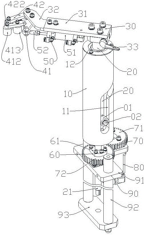
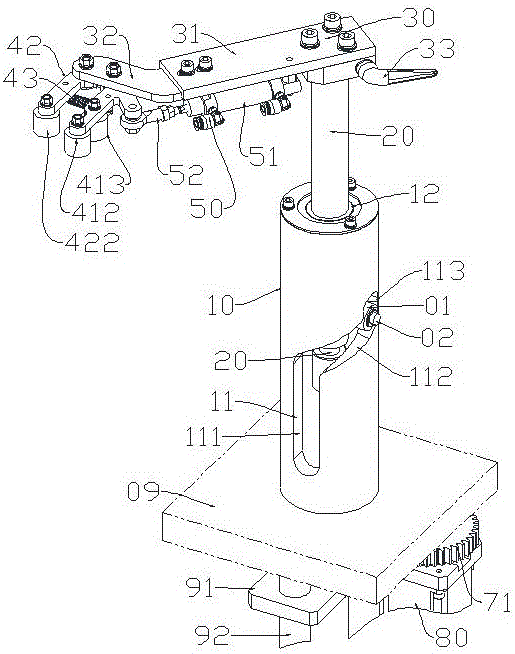
[0047] like figure 1 and figure 2 as shown, figure 1 A three-dimensional schematic view of the bottle-discharging manipulator provided by a specific embodiment of the present invention, showing that the lifting shaft is located at the bottom and the split jaws are in a tensioned state; figure 2 for figure 1 The thr...


PUM


Abstract

The invention discloses a bottle discharge mechanical hand which comprises a lifting shaft base, a rotary lifting shaft arranged on the lifting shaft base, and a clamping installing base arranged on the top of the lifting shaft. The lifting shaft is provided with an idler wheel and an idler wheel shaft. A sliding type claw and a claw control mechanism are arranged at the front end of the clamping installing base. The lifting shaft base is provided with a cam groove which is matched with the idler wheel and enables the lifting shaft to be rotated in an orienting mode in the lifting process. The vertical part of the bottle discharge mechanical hand is small in occupied space. When the bottle discharge mechanical hand is arranged on a bottle manufacturing machine, the clamping installing base can be arranged roughly along the tangent line of a rotating disc of the bottle manufacturing machine or the position parallel to the tangent line, the direction of moving glass bottles out can be the direction perpendicular to the rotary disc of the bottle manufacturing machine roughly, a follow-up discharging device can be arranged conveniently, arrangement space needed by equipment is greatly reduced, and the space utilization rate is increased. The invention further provides the bottle manufacturing machine adopting the bottle discharge mechanical hand and the glass bottles manufactured by the bottle manufacturing machine.

Description

technical field [0001] The present application relates to the technical field of glass bottle manufacturing equipment and the technical field of manipulators, and in particular relates to a bottle-discharging manipulator mainly used in a bottle-making system to take out finished products and transfer them to a discharge port. The bottle-discharging manipulator is mainly used in the glass bottle making system, and can also be used in the plastic bottle and other bottle making systems. [0002] In addition, the present application also relates to a bottle-making machine using the above-mentioned bottle-discharging manipulator. [0003] In addition, the present application also relates to a glass bottle made by the above-mentioned bottle making machine. Background technique [0004] In the bottle making process, especially when controlled glass bottle production equipment is used for production, high-temperature flames are required during the forming process of glass bottles, ...

Claims


Application Information

Patent Timeline
IPC IPC(8): C03B35/04C03B9/44B25J11/00
CPCC03B35/04B25J11/005C03B9/44
Inventor 阳年生金清阳李雄忠
Owner CHANGSHA ZHIYUAN TECH
Why Eureka
Try Eureka