Combined air conditioning system for machine room and control method thereof

A computer room air conditioner and composite technology, which is applied in the direction of refrigerators, compressors, refrigeration components, etc., can solve the problem of unfavorable use of outdoor low-temperature air at the upper limit temperature, and achieve the effect of avoiding low heat transfer efficiency, small transmission work, and compact structure

Active Publication Date: 2016-08-31
ANHUI JUNJIE NEW ENERGY SCI & TECH CO LTD
View PDF14 Cites 23 Cited by
  • Summary
  • Abstract
  • Description
  • Claims
  • Application Information

AI Technical Summary

Problems solved by technology

This system makes up for the deficiencies of the previous two systems in terms of utilizing the cooling capacity of outdoor low-temperature air and ensuring indoor air quality. However, if the two working modes of compression refrigeration and heat pipe circulation refrigeration are switched at a certain temperature point, can the cooling capacity of the system be stable? Connection and reliable work, etc., are worthy of consideration; at the same time, the upper limit temperature of the heat pipe circulation is too low, which is not conducive to maximizing the use of the cooling capacity of the low-temperature outdoor air
[0004] Invention patent CN01278831.7 discloses an energy-saving refrigeration cycle device with a circulation pump. The use of the c

Method used


Image

  • Combined air conditioning system for machine room and control method thereof
  • Combined air conditioning system for machine room and control method thereof
  • Combined air conditioning system for machine room and control method thereof

Examples


Embodiment 1

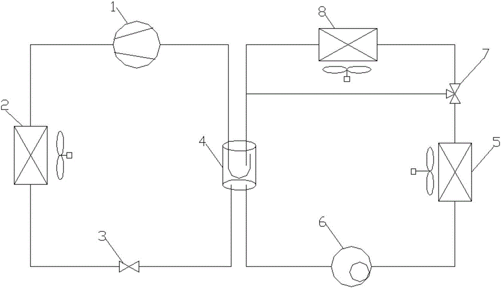
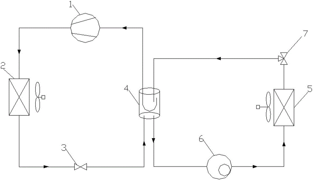
[0071] In summer, when the outdoor ambient temperature T is 33°C, which is greater than the preset temperature Tb, it is 25°C. At this time, it is determined that the operation mode of the air conditioning unit is the refrigeration cycle, and the temperature control device controls the three-way valve 7 to switch to the refrigeration cycle. Unit 1 is turned on and the heat exchange fan runs at full speed. The flow path of the refrigerant in a composite computer room air conditioning system is: from compressor 1 to refrigeration condenser 2, to throttling device 3 and low pressure accumulator 4. Then from the low-pressure accumulator 4 to the compressor 1 and refrigerant pump 6, the refrigerant from the refrigerant pump 6 to the evaporator 5, and then through the three-way valve 7, the low-pressure accumulator 4 and the refrigerant pump 6 in sequence; The outdoor environment temperature T is high, which makes the heat load of a composite computer room air-conditioning system larg...

Embodiment 2

[0083] When in spring or autumn, when the outdoor ambient temperature T is 22°C, lower than the preset temperature Tb is 25°C, and higher than the set temperature Ta is 15°C, the operation mode of the air conditioning unit is determined to be a combined cycle. , The temperature control device controls the three-way valve 7 to switch to the combined cycle. At this time, the compressor 1 is turned on and the heat exchange fan runs at full speed. The refrigerant flow path in a compound computer room air conditioning system is: from compressor 1 to refrigeration Condenser 2, then throttling device 3 and low-pressure accumulator 4, and then from low-pressure accumulator 4 to compressor 1 and refrigerant pump 6, and then the refrigerant from refrigerant pump 6 to evaporator 5, and then through Three-way valve 7, heat pipe condenser 8, low-pressure accumulator 4 and refrigerant pump 6; because the outdoor environment temperature T is low, the temperature control device controls a compo...

Embodiment 3

[0096] In winter, when the outdoor ambient temperature T is 8°C and the set temperature Ta is 15°C, the air conditioning unit operation mode is determined to be the heat pipe cycle, and the temperature control device controls the three-way valve 7 to switch to the heat pipe cycle. At this time, the compressor 1 is turned off, and the heat exchange fan runs at full speed or speed regulation. The flow path of the refrigerant in a composite computer room air-conditioning system is: from the refrigerant pump 6 to the evaporator 5, and then through the three-way Valve 7, heat pipe condenser 8, low pressure accumulator 4 and refrigerant pump 6; since the outdoor ambient temperature T is much lower than the temperature of the machine room, and sufficient cooling capacity can be provided to the machine room to maintain a suitable temperature in the machine room, Among the three control methods, the gaseous or gas-liquid mixed refrigerant flowing out of the indoor evaporator 5 exchanges ...


PUM


Abstract

The invention discloses a combined air conditioning system for a machine room and a control method thereof. The system comprises a refrigerating system, a heat tube unit and a three-way valve, wherein the refrigerating unit comprises one or a plurality of compressors, a refrigerating condenser, a throttling device and a low-pressure liquid storing device; the heat tube unit comprises the low-pressure liquid storing device, an evaporator, a refrigerant pump and a heat tube condenser; the refrigerating unit and the heat tube unit are coupled through the low-pressure liquid storing device. The combined air conditioning system for the machine room is characterized in that the temperature of a refrigerant in the low-pressure liquid storing device can be controlled and treated as the precise control parameter of system cold output; the three-way valve can be controlled to switch to correspondingly perform refrigerating circulating, combined circulating and heat tube circulating according to the outdoor environmental temperature, so as to meet the refrigerating demands of the machine room and a base station on all-weather air conditioning; the natural cold sources from day to night, transition season and winter can be utilized to the maximum. The system is compact in structure design, high in reliability, energy-saving, environmentally-friendly, high in thermal efficiency, high in stability, and high in adjusting accuracy.

Description

Technical field [0001] The invention relates to the technical field of air conditioners, in particular to a composite computer room air conditioning system and a control method thereof. Background technique [0002] The rapid development of the information industry and digital construction has promoted the number of computer rooms and base stations, and the scale of construction has grown rapidly. According to statistics, the energy consumption of air conditioners in computer rooms and base stations accounts for 40% to 50% of their total energy consumption. The sensible heat load ratio of the computer room and base station is large, and it needs to be operated continuously throughout the year. In the season when the indoor set temperature is lower than the outdoor temperature, the conventional air-conditioning system still needs to continue to operate the compression refrigeration system, which is low in efficiency and easy to occur. Failure, when the temperature difference betwe...

Claims


Application Information

Patent Timeline
IPC IPC(8): F25B1/00F25B41/00F25B49/02F25B41/40
CPCF25B1/00F25B49/022F25B41/40
Inventor 王君石文星史作君刘国旺
Owner ANHUI JUNJIE NEW ENERGY SCI & TECH CO LTD
Why Eureka
Try Eureka