
Particle swarm optimization based aerial conductor's double end out-synchronization fault location method

A technology of particle swarm algorithm and fault distance measurement, which is applied in the direction of fault location, fault detection according to conductor type, electrical measurement, etc., can solve problems such as complex technology, false roots in calculation results, and large investment

Inactive Publication Date: 2016-08-31
SHANGHAI MUNICIPAL ELECTRIC POWER CO +1
View PDF3 Cites 7 Cited by
  • Summary
  • Abstract
  • Description
  • Claims
  • Application Information

AI Technical Summary

Problems solved by technology

[0003] At present, the fault location research methods of transmission lines can be divided into two types according to the classification of data types. One is the traveling wave location method based on the fault transient quantity, which locates the fault point by calculating the time difference between the fault traveling wave arriving at both ends of the line. The method needs to develop special equipment, the technology is complicated and the investment is large, and it is difficult in engineering application; the second is the fault analysis method based on the fault steady-state quantity, which constructs redundant ranging equations by using the fault information on both sides of the line, so that In the case of reducing the influence of transition resistance, the fault point is located, but this method needs to realize the synchronization of data at both ends of the line, and the calculation result may have pseudo-roots

Method used


Image

  • Particle swarm optimization based aerial conductor's double end out-synchronization fault location method
  • Particle swarm optimization based aerial conductor's double end out-synchronization fault location method
  • Particle swarm optimization based aerial conductor's double end out-synchronization fault location method

Examples


Embodiment Construction

[0050] The present invention will be described in detail below in conjunction with the accompanying drawings and specific embodiments. This embodiment is carried out on the premise of the technical solution of the present invention, and detailed implementation and specific operation process are given, but the protection scope of the present invention is not limited to the following embodiments.

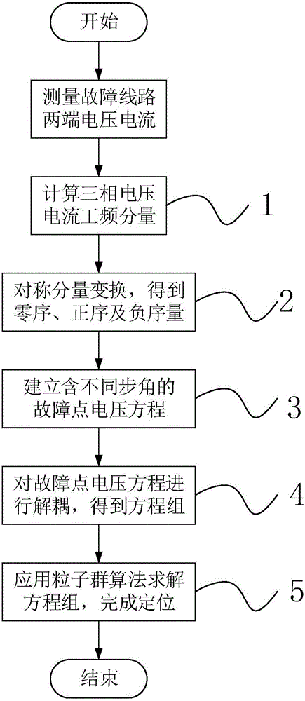
[0051] Such as figure 1 As shown, this embodiment takes a single-phase grounding short-circuit overhead line as the research object to perform double-terminal fault location, and locates the fault point according to the following steps:

[0052] Step 1: Apply the differential Fourier algorithm to the measured voltage and current data at both ends of the line to calculate the power frequency component of the three-phase voltage at the head end of the line when the overhead line is asymmetrical short-circuit fault The power frequency component of the three-phase current at the head en...


PUM


Abstract

The invention relates to particle swarm optimization based aerial conductor's double end out-synchronization fault location method with the object to solving a fault location observing equation set and the method comprises the following steps: extracting the three phases of voltage and current power frequency components at the starting end and the finishing end of a line after an aerial conductor breaks down; performing symmetrical component transformation to the work frequency components to obtain corresponding zero sequence component, positive sequence component and negative sequence component; building fault point voltage equations by considering the impact of the out-synchronization of data; decoupling the fault point voltage equations to obtain the fault location observing equation set; and based on the particle swarm optimization, solving the fault location observing equation set and determining the fault location. Compared to the prior art, the method is capable of effectively and accurately finding the location of a fault with limited calculations. With the prospects for wide use, the method is also convenient to calculate.

Description

technical field [0001] The invention relates to a relay protection method, in particular to a method for measuring the distance of a double-terminal asynchronous fault of an overhead line. Background technique [0002] The rapid development of the national economy and the increasing demand for electricity have made the structure of the power system increasingly complex. The transmission line undertakes the important task of transmitting electric energy, connecting the grid and electrical equipment, and is the basis for the safe and stable operation of the entire power system. However, the transmission line is also one of the parts with the most faults in the transmission network. Due to the wide distribution distance of the transmission line, and most of them pass through areas with relatively harsh natural environments, wind deviation, lightning strikes, icing and tree branch short-circuiting may cause transmission failures. Line short circuit fault. The above-mentioned ar...

Claims


Application Information

Patent Timeline
IPC IPC(8): G01R31/08
CPCG01R31/085G01R31/088
Inventor 吴家华华思明陆遥严倩倩计崔王丰华王劭菁穆卡张君
Owner SHANGHAI MUNICIPAL ELECTRIC POWER CO
Learn More