Common source double-frequency excitation type multifunctional micro-magnetic signal synchronous detection method

A detection method and signal synchronization technology are applied in the field of common-source dual-frequency excitation type multi-function micro-magnetic signal synchronization detection, which can solve the problems of long time consumption, incompletely consistent material magnetization states, and different "sources".

Active Publication Date: 2016-08-31
BEIJING UNIV OF TECH
View PDF6 Cites 17 Cited by
  • Summary
  • Abstract
  • Description
  • Claims
  • Application Information

AI Technical Summary

Problems solved by technology

[0003] In the published or public research results, for different micro-magnetic signals (Barkhausen noise, hysteresis loop, tangential magnetic field strength, eddy current, etc.), different excitation signals are often used for step-by-step excitation, which not only consumes The time is long and the magnetization state of the material is not completely consistent during the step-by-step test, and the "source" (material state) reflected by various signals is different

Method used


Image

  • Common source double-frequency excitation type multifunctional micro-magnetic signal synchronous detection method
  • Common source double-frequency excitation type multifunctional micro-magnetic signal synchronous detection method
  • Common source double-frequency excitation type multifunctional micro-magnetic signal synchronous detection method

Examples


Embodiment Construction

[0024] The present invention will be further described below in conjunction with the accompanying drawings and examples, and the following examples are only descriptive and not restrictive, and cannot be used to limit the protection scope of the present invention.

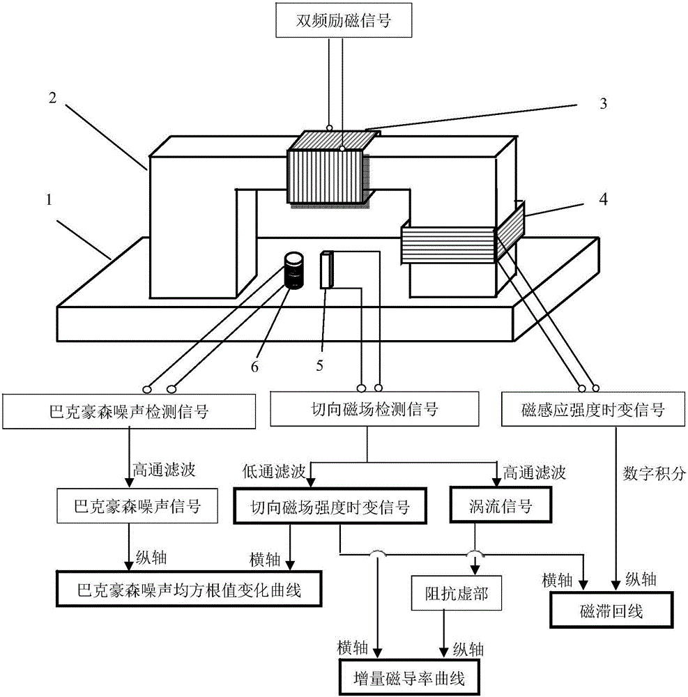
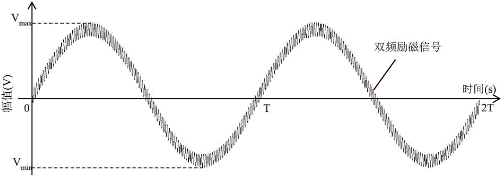
[0025] First, using a dual-frequency excitation signal (such as image 3 ) into the excitation coil 3 of the standard micro-magnetic probe to magnetize the tested ferromagnetic component 1, the induction coil 4 wound on the U-shaped magnetic core 2, the Hall element 5 placed on the surface of the tested ferromagnetic component 1 and the Barker The Hansoh noise detection coil 6 picks up the time-varying signal of the magnetic induction intensity synchronously (such as Figure 8 ), tangential magnetic field detection signal (such as Figure 4 ), Barkhausen noise detection signal (such as Figure 11 ). Second, follow the figure 1 In the signal processing method, the time-varying signal of the tangential magnetic ...


PUM


Abstract

A common source double-frequency excitation type multifunctional micro-magnetic signal synchronous detection method is disclosed and belongs to the technical field of micro-magnetic nondestructive testing. Via use of the common source double-frequency excitation type multifunctional micro-magnetic signal synchronous detection method, five types of typical micro-magnetic detection parameters can be obtained synchronously, and detecting efficiency can be greatly improved. A standard micro-magnetic probe comprises an excitation magnetic circuit consisting of a magnetic core and an excitation wire coil, an induction wire coil wounded around the magnetic core, a Hall element used for detecting surface tangential magnetic field change of a ferromagnetic component being detected, and a Barkhausen noise detection wire coil. Sine wave superposed signals having a low frequency less than 100 Hz and a high frequency greater than 1k Hz that matche with an amplitude ration are used as excitation signals, and the excitation signals are sent into the excitation wire coil of the standard micro-magnetic probe so as to magnetize the ferromagnetic component being detected. The induction wire coil, the Hall element and the Barkhausen noise detection wire coil are respectively used for synchronously picking characteristic signals such as magnetic induction intensity time-varying signals, tangential magnetic field detection signals and Barkhausen noise detection signals; magnetic hysteresis loops, tangential magnetic field intensity time-varying signals, Barkhausen noise, eddy current impedance and incremental magnetic permeability can be quickly detected.

Description

technical field [0001] The invention relates to a method for synchronously detecting multifunctional micro-magnetic signals of a common-source dual-frequency excitation type, and belongs to the technical field of micro-magnetic nondestructive testing. Background technique [0002] The optimal selection of excitation signal is one of the key technologies for micromagnetic measurement of mechanical properties of materials and structural components. [0003] In the published or public research results, for different micro-magnetic signals (Barkhausen noise, hysteresis loop, tangential magnetic field strength, eddy current, etc.), different excitation signals are often used for step-by-step excitation, which not only consumes The time is long and the magnetization state of the material is not completely consistent during the step-by-step test, and the "source" (material state) reflected by various signals is different. Therefore, the optimal selection of the excitation signal i...

Claims


Application Information

Patent Timeline
Patent Type & Authority Applications(China)
IPC IPC(8): G01R33/07G01R33/12G01R33/14
CPCG01R33/07G01R33/1223G01R33/14
Inventor 何存富闫杰刘秀成吴斌
Owner BEIJING UNIV OF TECH
Why Eureka
Try Eureka