
Spinous process and vertebral plate stabilizer

A technology of stabilizer and spine plate, applied in the direction of spinal implants, etc., can solve the problems of low complication long-term effect, weak resistance to elastic attenuation, impossibility of prosthetic placement, etc., to reduce the difficulty and risk of surgery, and resist The effect of strong elastic attenuation ability and reasonable structural design

Inactive Publication Date: 2016-09-07
李照文
View PDF8 Cites 6 Cited by
  • Summary
  • Abstract
  • Description
  • Claims
  • Application Information

AI Technical Summary

Problems solved by technology

[0004] However, there are still many defects in the existing interspinous process dynamic internal fixator.
[0005] For example, the Coflex system designed and provided by Samani in 1994 has a "U" shape when viewed from the side, and there are two "clip-shaped" fixed wing structures (one front and one rear) at the upper and lower ends of the U-shaped main structure. The upper and lower spinous processes are clamped and fixed; however, the fixed part of the system and the spinous process is a square structure, which does not match the anatomical structure of the spinous process, resulting in the need to use forceps to stretch and deform the flanks in a large range during installation After installation, it needs to be clamped and deformed in a large range, which makes the operation complicated during installation, and even fatigue and fracture of the flanks occur, and only sagittal extension and flexion can be provided.
Chinese invention patent (patent number: ZL201020247832.0) discloses a "spinal non-fusion fixation device", which has basically the same structure as the Coflex system, specifically, in the scheme of the invention patent, the U-shaped part 1 Corresponding to the U-shaped main structure of Coflex, the front and rear fixing plates 2 of the fixing part correspond to the two "clip-shaped" fixing wing structures of Coflex, and the front and rear fixing plates 2 are respectively fixed to two adjacent spines by screws. To achieve the fixation of the U-shaped main structure, but, as mentioned above, this structure can only achieve the extension and flexion of the sagittal position, that is, the size of the U-shaped opening is changed through the deformation of the U-shaped structure, so that the Cooperating with the change of the distance between spinous processes (inter-spinous) in the direction of opening and closing, the vertical support force of this large U-shaped structure is poor, and the ability to resist elastic attenuation is weak
[0006] The applicant of this application has also applied for an "interspinous stabilizer", patent number: 201520426702.6. However, due to the large structure volume of this technology during clinical use, the prosthesis cannot be placed into the hard disk during the operation. Therefore, the center of rotation of the prosthesis is far away from the center of rotation of the human lumbar spine when the human lumbar spine is twisted, that is, rotated in the coronal position. The operation is complicated when screw fixation is used, and the screw has the risk of loosening. Excessively large, adding new lumbar instability factors
[0007] The ideal interspinous process or interspinous plate dynamic internal fixation system should be able to generate continuous and sufficient distraction force at the bottom of the spinous process after implantation, so as to restore the height of the intervertebral space, increase the height of the intervertebral foramen, and make the infolded yellow The ligaments are opened in reverse to reduce their invasion into the spinal canal, increase the volume of the spinal canal, and at the same time maintain good dynamic activities such as extension and flexion of the spine, but the existing dynamic internal fixation systems between spinous processes or spinous plates often cannot At the same time, it has good and continuous vertical stretching force and universal mobility
[0008] The activities of the human spine include extension and flexion in the sagittal position, lateral bending in the left and right directions, rotation in the coronal position, and a circle formed by comprehensive motion in multiple directions, but the existing dynamic internal fixator between spinous processes or spinous plates It is difficult to match the physiological activity patterns of the human spine, some of which can only move in one direction, some stress is easy to concentrate in a certain place and cause the prosthesis to break, some prosthesis and spinous processes cause wear and tear reactions, and some are long When used for a long time, its elastic structure has weak anti-elastic attenuation ability, some have poor vertical support, and some cannot realize that the rotation center of the prosthesis is close to the rotation center of the human lumbar spine on the coronal position and the rotation center on the sagittal position at the same time. Therefore, there are problems such as poor matching with the physiological activity pattern of the human lumbar spine, and it is difficult to guarantee low complications and good long-term effects

Method used


Image

  • Spinous process and vertebral plate stabilizer
  • Spinous process and vertebral plate stabilizer
  • Spinous process and vertebral plate stabilizer

Examples


Embodiment Construction

[0036] In order to make the purpose of the present invention, technical solutions and advantages clearer, the following will be combined with the appended Figure 1-10, clearly and completely describe the technical solutions of the embodiments of the present invention.

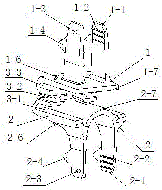
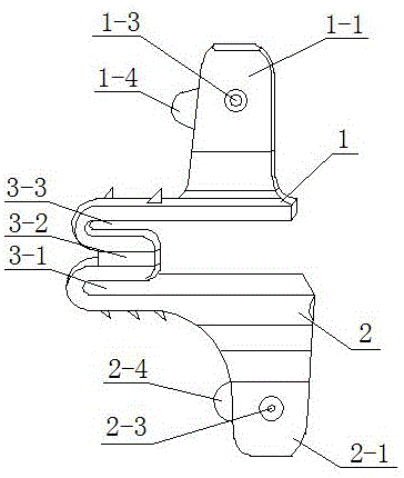
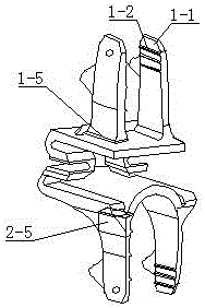
[0037] The inter-ratchet stabilizer includes a first fixing part 1 , a second fixing part 2 and an elastic device 3 , wherein the first fixing part 1 is connected to the second fixing part 2 through the elastic device 3 . Since the size and shape of the adjacent spinous processes are inconsistent, the first fixing part 1 and the second fixing part 2 can have an asymmetric structure, which is also conducive to better matching with the spinous process bone. But optionally, according to different application situations, the first fixing part 1 and the second fixing part 2 may also adopt a symmetrical structure.

[0038] The first fixing part 1 is composed of two side wings a1-1 and a bottom plate 1-7 to form a p...


PUM


Abstract

The invention relates to a spinous process and vertebral plate stabilizer, and belongs to the technical field of an elastomer for vertebral plate dynamic fixation. The spinous process and vertebral plate stabilizer includes a first fixing portion, a second fixing portion, and an elastic device; the first fixing portion is connected to the second fixing portion through the elastic device; a first fixing portion is of a clamp-shaped structure formed by two side wings a and a bottom plate; the second fixing portion is of a clamp-shaped structure formed by two side wings b and an arc bottom plate; and the elastic device consists of a first elastic structure, a second elastic structure and a third elastic structure. The spinous process and vertebral plate stabilizer fully considers the demands of physiological actions of a human body, can achieve maximum matching with the activity in all the directions, is reasonable in structure, is strong in vertical support force, is small in size, is reliable in fixation, and is high in elasticity attenuation resistance ability and can be used for the human body in a long term; rotation centers of a coronal view and a sagittal view of a prosthesis are close to rotation centers of a coronal view and a sagittal view of a spine of the human body after the stabilizer is implanted; and the spinous process and vertebral plate stabilizer is conductive to postoperative recovery of a patient, is easy to operate, and can lower the difficulty and risks of an operation.

Description

technical field [0001] The invention relates to an inter-spinous plate stabilizer, which belongs to the technical field of elastic bodies for dynamic fixation between spinous processes and lamina of the spine. Background technique [0002] At present, spinal fusion technology has achieved good results in the treatment of low back pain and cervical and lumbar instability, with a fusion rate of over 90%. However, studies have shown that its clinical efficacy has not reached the expected value; moreover, rigid internal fixation and spinal fusion may cause complications such as accelerated degeneration of adjacent segments, internal fixation failure, and postoperative pseudarthrosis formation. In view of this, dynamic fixation of the spine is becoming a popular technique in the treatment of degenerative cervical and lumbar diseases in recent years, including artificial total intervertebral disc replacement, artificial nucleus pulposus replacement, transpedicular dynamic fixation...

Claims


Application Information

Patent Timeline
Patent Type & Authority Applications(China)
IPC IPC(8): A61F2/44
CPCA61F2/44
Inventor 李照文
Owner 李照文
Learn More