Auxiliary electric rear axle of front-drive vehicle

A rear axle and vehicle technology, which is applied to vehicle components, electric power units, power units, etc., can solve the problems of insufficient traction of front-drive vehicles, and achieve the effects of small parasitic power loss, simple structure, and low cost

Inactive Publication Date: 2016-09-07
丁德胜 +1
View PDF9 Cites 2 Cited by
  • Summary
  • Abstract
  • Description
  • Claims
  • Application Information

AI Technical Summary

Problems solved by technology

[0008] The invention provides an auxiliary electric axle of a front-drive vehicle, which is used to solve the problem that the front-drive vehicle tends to have insufficient traction on complex road surfaces

Method used


Image

  • Auxiliary electric rear axle of front-drive vehicle
  • Auxiliary electric rear axle of front-drive vehicle
  • Auxiliary electric rear axle of front-drive vehicle

Examples


Embodiment 1

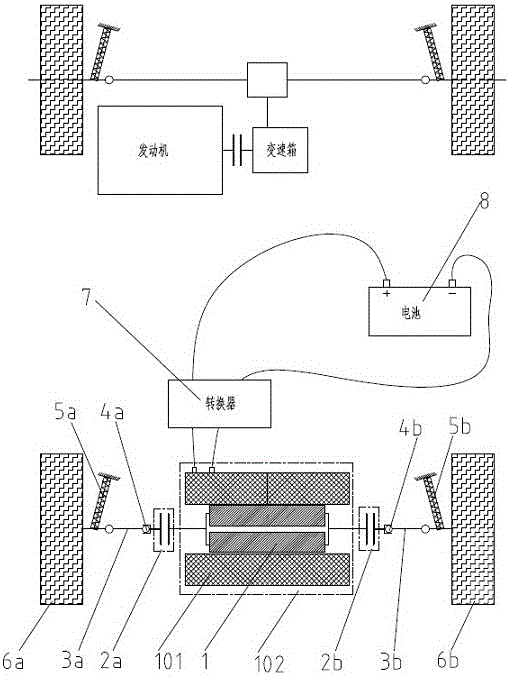
[0019] combined with figure 1 , specific embodiment 1 is described:

[0020] The auxiliary electric rear axle of the front-drive vehicle according to the present invention is composed of a main drive motor 1, a rear axle transmission clutch group 2, a half shaft 3, a universal joint 4, a suspension 5, a driving wheel 6, a battery converter 7 and a battery 8 .

[0021] Rear axle transmission clutch group 2 is composed of left clutch (2a) and right clutch (2b), half shaft 3 is composed of left half shaft (3a) and right half shaft (3b), universal joint 4 is composed of left universal joint (4a ) and the right universal joint (4b).

[0022] The main drive motor 1 is composed of an excitation coil 101 and a rotor 102. In order to realize the recovery of braking energy during the running of the vehicle, the main drive motor adopts the coaxial configuration of the rotor 102 and the left half shaft 3a and the right half shaft 3b. The main drive motor 1 The power is related to the ...

Embodiment 2

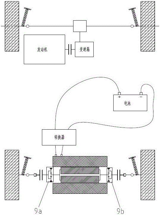
[0030] combined with figure 2 , the specific embodiment 2 is described: on the basis of embodiment 1, in order to further improve the load characteristics of the main drive motor 1, the rear axle transmission clutch set 2 is connected with the main drive motor 1 through a reducer 9. Reducer 9 adopts a planetary gear mechanism, that is, a planetary gear reducer, which can keep the coaxial connection of rear axle transmission clutch group 2 and main drive motor 1 .

Embodiment 3

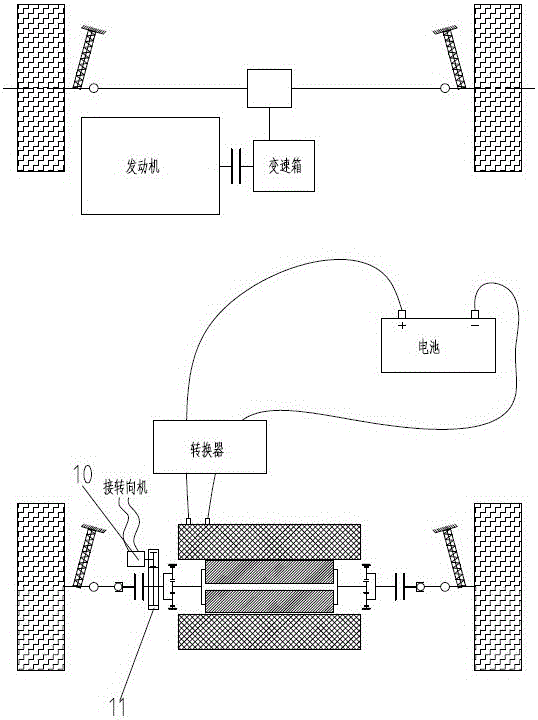
[0032] combined with image 3 , to illustrate the specific embodiment 3: in the state of engine flameout, in order to ensure that the off-road vehicle can be driven purely by the main drive motor 1, on the basis of the specific embodiment 2, install between the left reducer 9a and the left clutch 2a Transfer case 11, the transfer case 11 has a structure of an input shaft and two output shafts, the output shaft 1 of the transfer case 11 is connected with the left clutch 2a, and the output shaft 2 of the transfer case 11 is connected with the hydraulic pump 10.

[0033] Working principle: When the fuel of the off-road vehicle is exhausted, the engine cannot be started. At this time, the battery 9 supplies power to the main drive motor 1 to drive the vehicle. At the same time, the main drive motor 1 drives the hydraulic pump 12 through the transfer case 11 to provide hydraulic oil to the steering system. , to ensure the normal operation of the steering system of off-road vehicles...


PUM


Abstract

The invention discloses an auxiliary electric rear axle of a front-drive vehicle, belongs to the field of auxiliary drive of wheeled vehicles, and solves the problem that complex pavements easily cause insufficient traction. The auxiliary electric rear axle of the front-drive vehicle comprises a main drive motor, a rear axle transmission clutch group, semi-axles, universal joints, suspensions, driving wheels, a battery converter and a battery. The main drive motor is arranged to be coaxial with the rear axle transmission clutch group and the semi-axles; the rear axle transmission clutch group is composed of a left clutch and a right clutch which are arranged between the main drive motor and the semi-axles and arranged bilaterally symmetrical; the left clutch and the right clutch are connected with the semi-axles through the universal joints; the battery outputs stable direct current, and the main drive motor is driven through the battery converter; the battery converter converts the direct current output by the battery into the alternating current required by the drive motor.

Description

technical field [0001] The invention relates to an auxiliary drive system of a front drive off-road vehicle, which belongs to the field of auxiliary drive of wheeled vehicles. [0002] In addition, the present invention also relates to an electric axle of a gasoline-electric hybrid vehicle, the electric axle can selectively participate in the driving or braking process of the vehicle as required. Background technique [0003] Front-wheel-drive multifunctional off-road vehicles (SUVs) have occupied a certain amount of the automobile market, but they have the commonality of two-wheel drive vehicles, that is, they are prone to lack of traction on complex road surfaces. Compared with the front-wheel-drive off-road vehicle, in order to eliminate parasitic power, the structure of the four-wheel-drive off-road vehicle needs to increase the transfer case, inter-axle differential, rear-axle differential, inter-axle differential lock, and rear-axle differential. Locks and differentia...

Claims


Application Information

Patent Timeline
Patent Type & Authority Applications(China)
IPC IPC(8): B60K1/00B60K17/02B60K17/04
CPCB60K1/00B60K17/02B60K17/04B60K2001/001
Inventor 丁德胜梁燚杰
Owner 丁德胜
Why Eureka
Try Eureka