Pushing method and device for middle span of prestressed concrete box girder continuous rigid frame bridge with long span and high pier

A concrete box girder and prestressing technology, which is applied to bridges, bridge construction, erection/assembly of bridges, etc., can solve the problems of cumbersome installation of jacking devices, influence of box girders by force, and reduced construction quality, so as to save jacking preparation time, The effect of reducing the additional bending moment and shortening the construction period

Active Publication Date: 2017-07-18
SHANDONG UNIV OF SCI & TECH
View PDF5 Cites 0 Cited by
  • Summary
  • Abstract
  • Description
  • Claims
  • Application Information

AI Technical Summary

Problems solved by technology

[0004] At present, the multi-purpose jacking device will push the four corners of the box girder. The installation of the jacking device is relatively cumbersome and the construction is inconvenient.
There are also construction methods that anchor the pushing member and the roof of the box girder together, so that holes are inevitably opened in the roof of the box girder, causing stress concentration and affecting the force of the box girder, which in turn is extremely unfavorable for pushing and reduces the construction quality.
Due to the inhomogeneity of the concrete material or the installation position and device performance of other existing pushing devices and the additional bending moment caused by other uncontrollable factors, the force will be unstable during the pushing

Method used


Image

  • Pushing method and device for middle span of prestressed concrete box girder continuous rigid frame bridge with long span and high pier
  • Pushing method and device for middle span of prestressed concrete box girder continuous rigid frame bridge with long span and high pier
  • Pushing method and device for middle span of prestressed concrete box girder continuous rigid frame bridge with long span and high pier

Examples


Embodiment Construction

[0026] In order to make the objects and advantages of the present invention clearer, the present invention will be further described in detail below in conjunction with the examples. It should be understood that the specific embodiments described here are only used to explain the present invention, not to limit the present invention.

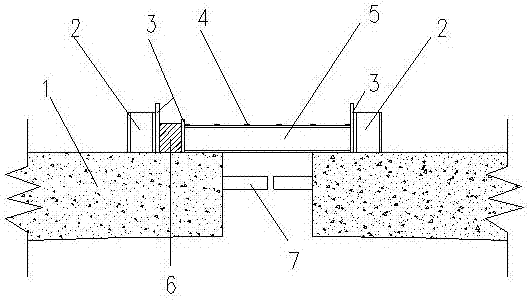
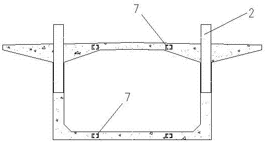
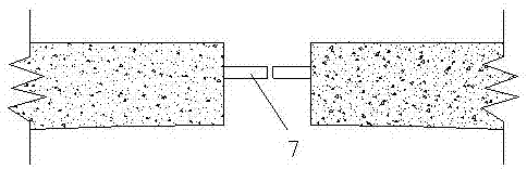
[0027] Such as Figure 1-Figure 4 As shown, the embodiment of the present invention provides a mid-span jacking device for a prestressed concrete box girder continuous rigid-frame bridge with long-span and high pier, which is characterized in that it includes a combined I-shaped steel beam 2, a backing plate 3, and a welded steel plate 4 , combined H-shaped steel beam 5, jack 6, stiff skeleton 7; described combined I-shaped steel beam 2 is welded by two I-shaped steel beams side by side, and described combined H-shaped steel beam 5 is formed by two H-shaped steel girders are welded side by side. The combined I-shaped steel beams 2 are buried ve...


PUM


Abstract

The invention discloses a mid-span jacking method and device for a prestressed concrete box girder continuous rigid frame bridge with long-span and high pier, which comprises a combined I-shaped steel girder, a backing plate, a welded steel plate, a combined H-shaped steel girder, a jack, Stiff skeleton; the combined I-shaped steel beam is welded by two I-shaped steel beams side by side, the combined H-shaped steel beam is welded by two H-shaped steel beams side by side, and the two ends of the box girder are vertical The combined I-shaped steel beams are directly buried, and the buried depth is 1 / 2 of the length of the web. Both sides of the steel mesh are welded to one end of the stiff frame along the longitudinal direction of the bridge, and the opposite stiff frames on both sides are on the same axis. The present invention directly installs the jacking device on the top of the box girder roof and pushes it, which greatly reduces the difficulty of construction operation, and can better ensure the quality of the jacking, the installation is simple and fast, and the preparation time for jacking is saved, thereby shortening the construction period and reducing the cost of construction. small cost.

Description

technical field [0001] The invention relates to the field of construction, in particular to a method and a device for pushing the middle span of a prestressed concrete box girder continuous rigid frame bridge with a large span and high pier. Background technique [0002] At present, my country's transportation is developing rapidly, and while the eastern coast is basically saturated, it continues to extend to the inland. Especially in the process of western development in recent years, people's requirements for driving speed and comfort have been continuously improved. Most of the various high-grade roads and railways pass through mountains and ridges, crossing deep ravines and ravines. The box girder continuous rigid frame bridge came into being. For long-span and high-pier prestressed concrete box girder continuous rigid-frame bridges, after the whole bridge is closed, due to temperature changes, concrete shrinkage and creep, and the second-stage dead load, the whole will...

Claims


Application Information

Patent Timeline
Patent Type & Authority Patents(China)
IPC IPC(8): E01D21/00
CPCE01D21/00
Inventor 张宪堂刘丹丹牟翠翠周红敏郭宁崔维征张立明王清王洪立
Owner SHANDONG UNIV OF SCI & TECH
Why Eureka
Try Eureka