Adjusting device of mixed flow water turbine

A technology of adjusting device and water turbine, which is applied in the direction of fluid pressure actuating device, safety device, engine sealing, etc., can solve the problems of shortening the maintenance time of the relay, difficult control of movable guide vanes, low reliability, etc., and achieves a small occupied space. , The effect of small radial displacement and low maintenance cost

Active Publication Date: 2016-09-07
浙江国正安全技术有限公司
View PDF5 Cites 0 Cited by
  • Summary
  • Abstract
  • Description
  • Claims
  • Application Information

AI Technical Summary

Problems solved by technology

[0003] However, the existing hydraulic turbines control the movable guide vanes through the control ring, which is basically realized by installing two servomotors. In this way, when a servomotor is damaged or needs to be repaired, it makes it very difficult to control the movable guide vanes. not tall
When the existing Francis turbine adjusts the movable guide vane to a proper position, the opening of the guide vane is maintained by the locking device installed on the servomotor. Usually, the locking device can only be locked at the full close or the maximum opening. , so that the load of the servomotor continues, the maintenance time of the servomotor is shortened, and the possibility of oil leakage of the servomotor is increased

Method used


Image

  • Adjusting device of mixed flow water turbine
  • Adjusting device of mixed flow water turbine
  • Adjusting device of mixed flow water turbine

Examples


Embodiment 1

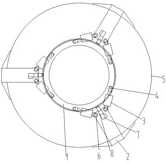
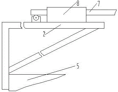
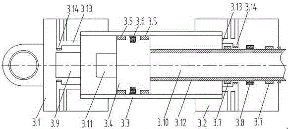
[0033] Such as figure 1 , figure 2 and image 3 The adjustment device of the Francis turbine shown includes control ring 1, support base 2, servomotor 3, A cylinder head 3.1, B cylinder head 3.2, cylinder barrel 3.3, piston 3.4, guide ring 3.5, trapezoidal seal groove 3.6, guide Groove 3.7, sealing groove 3.8, buffer groove 3.9, piston rod 3.10, buffer head 3.11, sleeve 3.12, through hole 3.13, sedimentation tank 3.14, fixed rod 4, top cover 5, support rod 6 and limit rod 7, for The control ring 1 that controls the opening of the movable guide vane is installed on the top cover 5 of the water turbine, and three support seats 2 are equidistantly installed on the outer wall of the top cover 5, and each support seat 2 is symmetrically provided with two vertical support rods 6. There are six uniformly distributed fixed rods 4 on the top surface of the control ring 1, and the two ends of the servomotor 3 are respectively connected to the fixed rods 4 and the support rods 6 by ro...

Embodiment 2

[0037] Such as figure 1 , figure 2 and Figure 4 The adjustment device of the Francis turbine shown includes control ring 1, support base 2, servomotor 3, A cylinder head 3.1, B cylinder head 3.2, cylinder barrel 3.3, piston 3.4, guide ring 3.5, trapezoidal seal groove 3.6, guide Groove 3.7, sealing groove 3.8, buffer groove 3.9, piston rod 3.10, buffer head 3.11, sleeve 3.12, through hole 3.13, sedimentation tank 3.14, fixed rod 4, top cover 5, support rod 6 and limit rod 7, for The control ring 1 that controls the opening of the movable guide vane is installed on the top cover 5 of the water turbine, and three support seats 2 are equidistantly installed on the outer wall of the top cover 5, and each support seat 2 is symmetrically provided with two vertical support rods 6. There are six uniformly distributed fixed rods 4 on the top surface of the control ring 1, and the two ends of the servomotor 3 are respectively connected to the fixed rods 4 and the support rods 6 by r...


PUM


Abstract

The invention discloses an adjusting device of a mixed flow water turbine. The adjusting device comprises a control ring, supporting bases and servomotors. The three supporting bases are installed on the outer side wall of a top cover at equal interval. Each supporting base is symmetrically provided with two vertical supporting rods. Six evenly-distributed fixing rods are arranged on the top face of the control ring. The two ends of each servomotor are rotationally connected to the fixing rods and the supporting rods. Straight teeth are evenly arranged on the upper edge of the control ring. The three supporting bases are each provided with a limiting rod. One end of each limiting rod is provided with straight teeth matched with the straight teeth on the upper edge of the control ring. The straight tooth ends of the limiting rods are installed towards the center of the control ring. The limiting rods are provided with straight teeth installed in cooperation with gears which are installed in cooperation with servo motors. The limiting rods are provided with limiting sleeves which are fixedly installed on the supporting bases. According to the technical purpose of the adjusting device of the mixed flow water turbine, the limiting rods are arranged to lock the control ring, and the six servomotors are arranged and distributed on the top of the control ring.

Description

technical field [0001] The invention relates to the field of water turbines, in particular to an adjusting device for a Francis water turbine. Background technique [0002] The control of the movable guide vanes of the water guide mechanism of the existing Francis turbines is mostly realized through the control of the control ring, and some of them are directly controlled by directly acting on the movable guide vanes through the servomotor. [0003] However, the existing hydraulic turbines control the movable guide vanes through the control ring, which is basically realized by installing two servomotors. In this way, when a servomotor is damaged or needs to be repaired, it makes it very difficult to control the movable guide vanes. not tall. When the existing Francis turbine adjusts the movable guide vane to a proper position, the opening of the guide vane is maintained by the locking device installed on the servomotor. Usually, the locking device can only be locked at the ...

Claims


Application Information

Patent Timeline
IPC IPC(8): F03B3/18F03B15/06F16J15/16F15B15/20F15B19/00
CPCF03B3/183F03B15/06F05B2270/602F05B2270/604F15B15/1433F15B15/1461F15B15/1471F15B19/005Y02E10/20
Inventor 王欢
Owner 浙江国正安全技术有限公司
Why Eureka
Try Eureka