Box structure for tunnel sterilizing dryer and laminar flow control method of box

A box structure and dryer technology, which is used in drying solid materials, drying gas layout, dryers, etc., can solve the problems of inconvenient inspection and maintenance of internal structures, low space utilization of air flow passages, and unfavorable control of air flow uniformity. and other problems, to achieve the effect of convenient plant layout, obvious lamination effect, and better uniformity of hot air

Inactive Publication Date: 2016-09-07
TRUKING TECH LTD
View PDF6 Cites 5 Cited by
  • Summary
  • Abstract
  • Description
  • Claims
  • Application Information

AI Technical Summary

Problems solved by technology

[0003] Due to the existing technical schemes that basically use split external circulation in the preheating section and cooling section, a large amount of wind needs to be collected from indoors or outdoors, which is not convenient for the air pressure balance control in the washing and drying room. The lower temperature causes the bottle to explode due to the excessive temperature difference after entering the high temperature section, and the internal structure of each box is relatively complicated, which increases the cost of materials and processing, and is not convenient for the inspection and maintenance of the internal structure. The space utilization rate of the internal air flow channel of the body is not high, which is not conducive to the control of air flow uniformity

Method used


Image

  • Box structure for tunnel sterilizing dryer and laminar flow control method of box
  • Box structure for tunnel sterilizing dryer and laminar flow control method of box
  • Box structure for tunnel sterilizing dryer and laminar flow control method of box

Examples


Embodiment 1

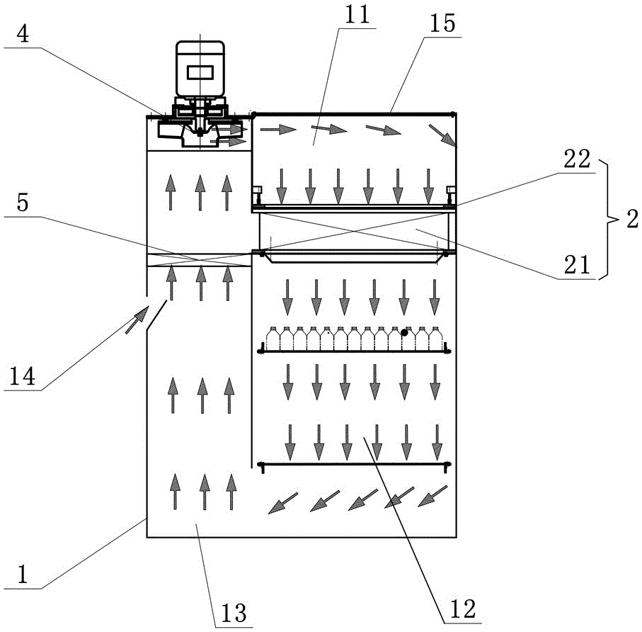
[0027] Such as figure 1 As shown in the first embodiment of the box structure for the tunnel type sterilization dryer of the present invention, the inside of the box 1 is provided with a first cavity 11, a second cavity 12 and a return air cavity in sequence from top to bottom. 13. The bottom of the first cavity 11 communicates with the top of the second cavity 12, the two ends of the return air cavity 13 communicate with the first cavity 11 and the second cavity 12 respectively, and the bottom of the first cavity 11 is equipped with a filter The box body 1 is equipped with a fan assembly 4 for introducing air into the first cavity 11 near the top of the air return cavity 13 . As shown by the arrow in the figure, the fan assembly 4 inhales the gas and then pressurizes it and discharges it into the first cavity 11 to achieve the purpose of continuous blowing. The air flow flows downward from the first cavity 11 to the filter assembly 2 for filtering, and then Enter the second ...

Embodiment 2

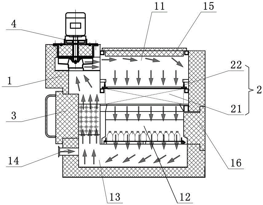
[0034] Such as figure 2 As shown, the second embodiment of the box structure for the tunnel type sterilization dryer of the present invention, the box 1 is basically the same as that of the embodiment 1, the only difference is that: the side of the box 1 is installed to extend to the return air cavity 13 inside the heating element 3. The heating assembly 3 is mainly used to heat the air flowing in from the preheating section and the air flowing in from the supplementary air outlet. The box structure is suitable for the heating section of the tunnel type sterilization dryer. The air flow of the heating section structure also adopts the internal circulation mode. Under the adsorption load of the high-temperature laminar flow fan assembly 4, it is blown into the first cavity 11 composed of the filter assembly 2 and the top door 15. Since the air flow space is relatively large, it is blown vertically to the filter 21 by utilizing the lamination effect of the air flow. After the ...

Embodiment 3

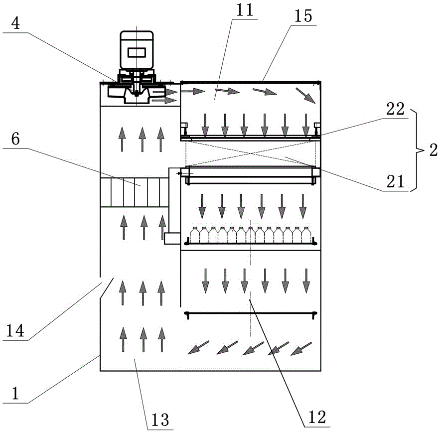
[0037] Such as image 3 As shown, the third embodiment of the cabinet structure for the tunnel type sterilization dryer of the present invention, the cabinet 1 is basically the same as that of Embodiment 1, the only difference is that a surface cooler assembly 6 is installed in the return air cavity 13 . The surface cooler assembly 6 is mainly used to cool the air flowing in from the supplementary air inlet. The box structure is suitable for the cooling section of the tunnel type sterilization dryer. The air flow of the cooling section structure also adopts the internal circulation mode. 4 is blown into the first cavity 11 formed by the filter assembly 2 and the top door 15 under the action of the adsorption load of 4. Since the air flow space is relatively large, the lamination effect of the air flow is used to vertically blow to the filter 21, and the air flow blows to the filter 21 after being filtered. The bottle body in the second chamber 12 is cooled and cooled, and the...


PUM


Abstract

The invention discloses a box structure for a tunnel sterilizing dryer and a laminar flow control method of a box. The box structure is internally provided with a first cavity channel, a second cavity channel and an air return cavity channel sequentially from top to bottom; the bottom part of the first cavity channel communicates with the top part of the second cavity channel; two ends of the air return cavity channel respectively communicate with the first cavity channel and the second cavity channel; a filter assembly is arranged on the bottom part of the first cavity channel; a fan assembly used for guiding air into the first cavity channel is arranged on the top part, close to the air return channel cavity, of the box. The control method comprises the following steps that the fan assembly is started to guide the air into the first cavity channel, and the air is filtered by the filter assembly, then enters the second cavity channel to act on a bottle inside the second cavity channel, and finally returns to the fan assembly through the air return cavity channel to form inner circulation laminar flow. The box structure and the laminar flow control method have the advantages of simplicity, compactness, low cost, convenience in layout, and capability of improving the laminating effect and the hot air uniformity.

Description

technical field [0001] The invention mainly relates to the field of food and pharmaceutical packaging machinery, in particular to a box structure for a tunnel type sterilization dryer and a laminar flow control method for the box. Background technique [0002] Tunnel-type sterilizing dryers basically consist of three structures: preheating section, heating section, and cooling section. The air flow in the preheating section and the air-cooled cooling section usually adopts the external circulation mode, which is carried out from the washing room or outside. Wind collection, only the heating section uses internal circulation. The three structural sections are provided with a windshield assembly between the fan outlet position and the filter, and a return air frame assembly is provided under the mesh belt. [0003] Due to the existing technical schemes that basically use split external circulation in the preheating section and cooling section, a large amount of wind needs to ...

Claims


Application Information

Patent Timeline
IPC IPC(8): F26B25/00F26B21/02B65B55/06
CPCB65B55/06F26B21/003F26B21/02F26B25/00
Inventor 熊森冰曾宪喜
Owner TRUKING TECH LTD
Why Eureka
Try Eureka