
Unmanned aerial vehicle flight control method and control system

A flight control system and flight control technology, applied in the field of unmanned aerial vehicles, can solve the problems that the real-time performance of the flight control system cannot be guaranteed, data communication is easily affected by external interference, and the performance of the flight control system is affected, achieving fast speed and ensuring simplicity , cost reduction effect

Inactive Publication Date: 2016-09-07
深圳市金鹰悦飞科技有限公司
View PDF5 Cites 46 Cited by
  • Summary
  • Abstract
  • Description
  • Claims
  • Application Information

AI Technical Summary

Problems solved by technology

Since the UAV flight control system needs to be based on embedded real-time software and hardware, the system resources are limited, and more functions cannot be expanded. If a CPU with abundant resources is used, it must be equipped with a time-sharing system to manage many resources reasonably. However, the real-time performance of the elements required by the flight control system cannot be guaranteed, and the performance of the flight control system is greatly affected
[0003] At present, most UAV solutions use multiple processors to complete their respective functions, such as flight control processors, camera processors, and gimbal processors. Standard communication interfaces are provided between each processor, so that Although it is possible to exchange data, it requires a lot of communication protocols and a lot of software writing work. At the same time, data communication is easily disturbed by the outside world, and the timeliness of data is also limited.

Method used


Image

  • Unmanned aerial vehicle flight control method and control system
  • Unmanned aerial vehicle flight control method and control system
  • Unmanned aerial vehicle flight control method and control system

Examples


Embodiment Construction

[0047] The following will clearly and completely describe the technical solutions in the embodiments of the present invention with reference to the accompanying drawings in the embodiments of the present invention. Obviously, the described embodiments are only part of the embodiments of the present invention, not all of them. Based on the embodiments of the present invention, all other embodiments obtained by persons of ordinary skill in the art without creative efforts fall within the protection scope of the present invention.

[0048] It should be noted that all directional indications (such as up, down, left, right, front, back...) in the embodiments of the present invention are only used to explain the relationship between the components in a certain posture (as shown in the accompanying drawings). Relative positional relationship, movement conditions, etc., if the specific posture changes, the directional indication will also change accordingly.

[0049] In addition, in t...


PUM


Abstract

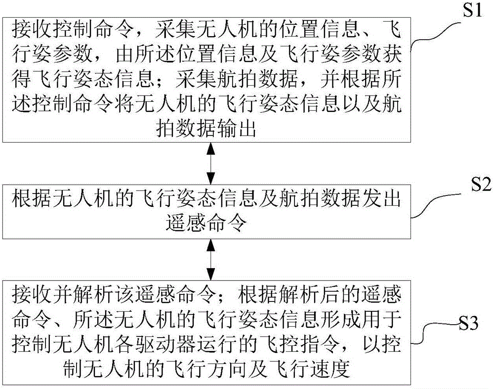
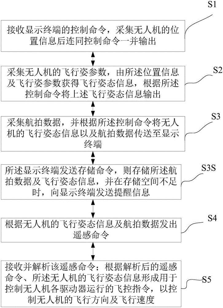
The invention discloses an unmanned aerial vehicle flight control method and an unmanned aerial vehicle control system. The method includes the following steps that: a control command is received, and the location information and flight attitude parameter of an unmanned aerial vehicle are acquired, and flight attitude information can be obtained according to the location information and the flight attitude parameter; aerial photography data are acquired, and the flight attitude information and the aerial photography data of the unmanned aerial vehicle are outputted according to the control command; a remote sensing command is sent out according to the flight attitude information and the aerial photography data of the unmanned aerial vehicle; the remote sensing command is received and analyzed; and a flight control command used for controlling the operation of the drivers of the unmanned aerial vehicle is formed according to the analyzed remote sensing command, and the flight attitude information of the unmanned aerial vehicle, so that the flight direction and flight speed of the unmanned aerial vehicle can be controlled. With the above technical schemes of the invention adopted, simplicity, security and real-time performance of data exchange can be improved.

Description

technical field [0001] The invention relates to unmanned aerial vehicle technology, in particular to an unmanned aerial vehicle flight control method and control system. Background technique [0002] With more and more UAV manufacturers, cost competition among various manufacturers has been put on the agenda, and it is particularly important to adopt new technologies to improve the overall performance of UAVs. Since the UAV flight control system needs to be based on embedded real-time software and hardware, the system resources are limited, and more functions cannot be expanded. If a CPU with abundant resources is used, it must be equipped with a time-sharing system to manage many resources reasonably. However, the real-time performance of the elements required by the flight control system cannot be guaranteed, and the performance of the flight control system is greatly affected. [0003] At present, most UAV solutions use multiple processors to complete their respective fu...

Claims


Application Information

Patent Timeline
IPC IPC(8): G05D1/08G05D1/10
CPCG05D1/0808G05D1/101
Inventor 徐小明
Owner 深圳市金鹰悦飞科技有限公司
Learn More