
A kind of chained statcom control method and system

A control method and chain-type technology, applied in flexible AC power transmission systems, output power conversion devices, irreversible DC power input conversion to AC power output, etc., can solve problems such as zero drift, initial value sensitivity, integral saturation, etc.

Active Publication Date: 2018-05-01
ELECTRIC POWER RESEARCH INSTITUTE, CHINA SOUTHERN POWER GRID CO LTD
View PDF4 Cites 0 Cited by
  • Summary
  • Abstract
  • Description
  • Claims
  • Application Information

AI Technical Summary

Problems solved by technology

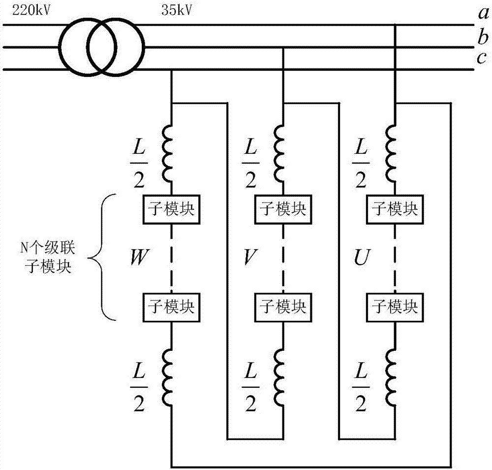
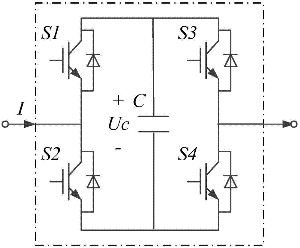
[0004] The invention provides a chained STATCOM control method and system, which solves the problems of initial value sensitivity, integral saturation, zero drift, and complex structure existing in the existing no-AC sensor control method

Method used


Image

  • A kind of chained statcom control method and system
  • A kind of chained statcom control method and system
  • A kind of chained statcom control method and system

Examples


Embodiment 1

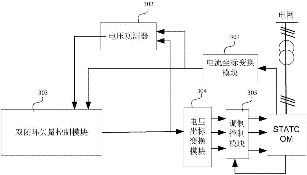
[0069] An embodiment of the present invention provides a chained STATCOM control system, see image 3 , the system includes:

[0070] The current coordinate transformation module 301 is used to collect the three-phase bridge arm current i of the STATCOM at the current moment uvw , and the three-phase arm current i at the current moment uvw After coordinate transformation, the bridge arm current i in the two-phase stationary coordinate system at the current moment is obtained αβ .

[0071] Wherein, the input end of the current coordinate transformation module 301 can be connected with the chained STATCOM for collecting the three-phase bridge arm current i of the STATCOM at the current moment uvw . The output terminals can be respectively connected with the voltage observer 302 and the inner loop control module of the double closed loop vector control module 303 .

[0072] Exemplarily, the current coordinate transformation module 301 can convert the three-phase bridge arm c...

Embodiment 2

[0124] An embodiment of the present invention provides a chained STATCOM control method, see Figure 7 ,include:

[0125] S701. Collect the current i of the three-phase bridge arm of the STATCOM at the current moment uvw , and the three-phase arm current i at the current moment uvw After coordinate transformation, the bridge arm current i in the two-phase stationary coordinate system at the current moment is obtained αβ .

[0126] S702. According to the bridge arm current i in the two-phase stationary coordinate system at the current moment αβ , and the reference voltage of the bridge arm at the previous moment at the current moment Calculate the observed value of the grid voltage at the STATCOM port at the current moment

[0127] Wherein, in step S702, the arm current i in the two-phase stationary coordinate system according to the current moment αβ , and the reference voltage of the bridge arm at the previous moment at the current moment Calculate the observed value...


PUM


Abstract

The invention provides a chained STATCOM control method and system, which solves the problems of initial value sensitivity, integral saturation, and zero drift in the existing non-AC sensor control method. The method includes: collecting the three-phase bridge arm of the STATCOM at the current moment current iuvw, and transform the three-phase bridge arm current iuvw at the current moment into the bridge arm current iαβ in the two-phase stationary coordinate system at the current moment; calculate according to the iαβ at the current moment and the bridge arm reference voltage at the previous moment at the current moment Obtain the observed value of the grid voltage at the STATCOM port at the current moment. According to the observed value of the grid voltage at the STATCOM port at the current moment and the bridge arm current iαβ, obtain the bridge arm voltage reference value under the two-phase static coordinate system at the current moment, and perform coordinate transformation on the bridge arm voltage reference value Obtain the reference voltage of the three-phase bridge arm to acquire the capacitor voltage Uc of the sub-module of the bridge arm, and obtain the switch signal of the sub-module through modulation control according to the reference voltage of the three-phase bridge arm.

Description

technical field [0001] The invention belongs to the field of electric energy conversion, and in particular relates to a chained STATCOM control method and system. Background technique [0002] With the development of electronic technology, chained STATCOM (Chinese: Static Synchronous Compensator, English: Stat icSynchronous Compensator), has been more and more widely used in the field of high-voltage and high-power transmission. Large-capacity chained STATCOMs are generally connected to the power grid through an interface transformer, and phase-locked control is performed by collecting high and low voltage side voltage and current. It is difficult for the existing control strategy to accurately distinguish the disconnection fault of the voltage sensor from the voltage fault on the low-voltage side. In both cases, the STATCOM will be blocked and tripped, so it is difficult to effectively support the voltage fault on the low-voltage side. In addition, the output error of the ...

Claims


Application Information

Patent Timeline
Patent Type & Authority Patents(China)
IPC IPC(8): H02J3/18H02M7/49
CPCH02J3/1857H02M7/49H02M1/007Y02E40/10
Inventor 龚文明朱喆冯满盈魏伟赵晓斌杨煜许树楷
Owner ELECTRIC POWER RESEARCH INSTITUTE, CHINA SOUTHERN POWER GRID CO LTD
Learn More